In this series of posts, I’ll be providing tips that show how to do something in both AutoCAD and BricsCAD, hence A & B.

The Series
The idea behind this series is to provide useful information for several sorts of reader:
- AutoCAD users.
- BricsCAD users.
- People in the process of transitioning from AutoCAD to BricsCAD and who need to know what to do differently (if anything).
- People considering transitioning from AutoCAD to BricsCAD and who want to know about the differences and similarities.
Realistic Threads
This post explains how to create realistic-looking threads for screws, nuts and the like in your presentation 3D models. I don’t suggest you do this routinely because it will add pointless complexity to your everyday models, but occasionally you will need to make a model that looks highly realistic. For example, you might need a photorealistic rendering of an assembly or an exploded view for a user manual. This example will use ISO metric parts, but the principles are the same for all threads. I’ll assume you have a basic understanding of creating 3D primitives and the boolean operations (union, subtract and intersect).
BricsCAD Standard Parts
The first thing to note is that unless you insist on the threads being helical, you probably have very little work to do. Have a look at this ISO M10 screw and bolt. It doesn’t have helical threads, but is it good enough for your needs?
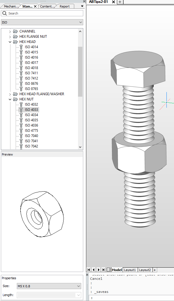
If so, and if you have BricsCAD Platinum, you can save yourself a lot of work. I created this model using the Standard Parts panel on the left. To create the nut, I used ISO > HEX NUT > ISO 4033 > M10 x 1.5. Having chosen my component, I just dragged and dropped it from the panel (the bit that’s highlighted above) into the drawing and specified an insertion point. The screw was similarly easy: ISO > HEX NUT > ISO 4018 > M10 x 1.5 and Length 50.
Here’s a close-up. This is good enough for most cases, but if you’re picky you can tell the threads aren’t helical. If you’re really, really picky you can tell that the threads aren’t the exactly correct profile (e.g. no flats on the peaks or troughs).
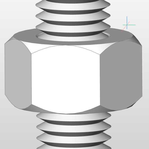
Also, getting really, really, really picky, there is neither a runout of the thread at the top nor a spherical end at the bottom. If that’s not good enough and you need to construct a model that provides a completely accurate representation, how can you do this? Read on.
Creating helical threads in BricsCAD and AutoCAD
I’m going to recreate the above screw as our example, but will make it dimensionally accurate. For simplicity, I’ll ignore the hex head and just do the shaft part. I’ll use BricsCAD to work through this, but it doesn’t matter. The steps are exactly the same in AutoCAD. There are a few things in BricsCAD’s 3D repertoire that might make things a little easier than in AutoCAD, but I won’t be using them here. I will be switching back and forth between visual styles in order to better show what’s going on with the geometry, so don’t expect consistency between the images.
First, construct a few basic parts from solid primitives. Here are the dimensions you’ll need for doing that:
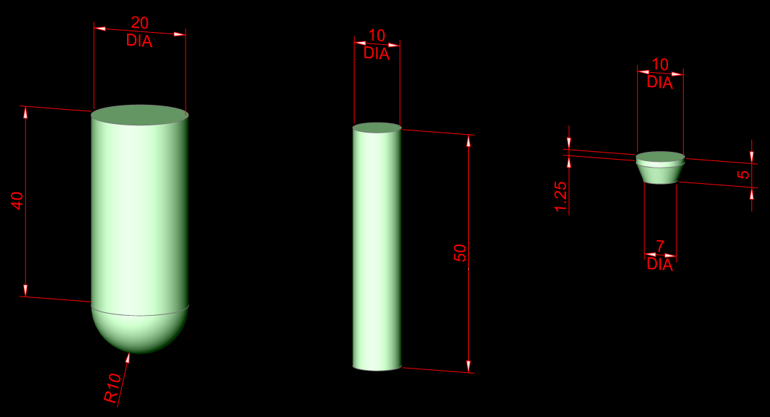
From left to right, we have:
- DIA 20 x 40 cylinder that has been unioned with an DIA 20 sphere
- DIA 10 x 50 cylinder
- DIA 10 x 1.25 cylinder that has been unioned with a truncated cone DIA 10 to 7 x 3.75
The next step is to create the thread. There are two parts to this: the path and the profile. The path is easy: we just use the HELIX command. Specify the center of the middle cylinder as the base, a base and top radius of 5 (but specify the base radius using a known point such as a quadrant), a turn height of 1.5 (that’s the thread pitch) and a height of 50.
You might be tempted to make a simplified profile using an equilateral triangle with a side length of 1.5 (the pitch). Hot tip: don’t do this. Unfortunately, this will cause problems. Both AutoCAD (usually) and BricsCAD (sometimes) may refuse to create the thread because it thinks it self-intersects. You can use a simple triangle profile, but you’ll need to make it slightly smaller than the pitch: scaling by a factor of 0.95 should do.
Instead, let’s do it more accurately. The profile can be created as a polyline using conventional 2D techniques. Here are the profile dimensions for an M10 x 1.5 thread:
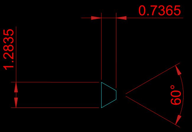
Note: to be completely accurate, the thread profile should also have a root radius. Feel free to add one if you like.
Either draw this profile in place using an appropriate UCS such that it is vertical up against the middle cylinder, or draw it in WCS and then move it into place using the ALIGN command. Although having the profile located in the right plane and location is theoretically not necessary, in practice it makes creating the thread much less fraught.
Here’s a tip that will save you a lot of trouble later: move the profile very slightly away from the center of the cylinder. A distance of, say, 0.01 will do. Here’s what it should look like if you zoom in far enough:
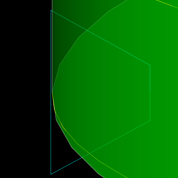
If you don’t do this, your CAD application will get into trouble later when you try to subtract the thread, because the outside of the thread and the cylinder will coincide, causing problems for the software. Having the outside of the thread just slightly beyond the edge of the cylinder will prevent this issue. Instead of kludging things by moving the profile slightly as described here, you could alternatively draw the profile such that it’s dimensionally accurate but with an outside edge slightly beyond the cylinder. Just make sure you don’t extend the profile so far that you run into the self-intersecting problem.
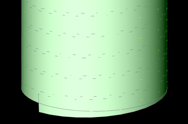
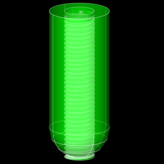
Next, use the SWEEP command, select the profile and the path. That should give you this:
Subtract the thread from the cylinder. Now move the cylinder/cone primitive into place on top of the shaft using CENter osnap and union the two solids, producing the elegant thread runout you see here:

Move the cylinder/sphere primitive into place on top of the shaft using CENter osnap:
Finally, intersect the two solids, producing this domed end to the threaded shaft:

Here’s the finished product in BricsCAD after I added a hex head to the top, unioned the solids together and added a brushed metal material.

Summary
The steps are the same in AutoCAD and BricsCAD:
- Create the primitive objects you’ll use later to define the threaded object
- Create a thread path using HELIX
- Create a thread profile polyline and move it into position
- Ensure the profile extends slightly beyond the edge of the shaft
- Use SWEEP to create the thread
- Subtract the thread from the shaft
- Move the cone/cylinder primitive into place and union the parts
- Move the sphere/cylinder primitive into place and intersect the parts
If you want to do this in a nut or hole, use the same principles. You just need to reverse the thread profile such that it’s pointing outwards into the hole before sweeping and subtracting.
Nice writeup Steve. Something I discovered about the sweep command, is it will fail to make the solid sometimes. Autocad handles this by doing nothing. Bcad will make the solid up to the spot it had issues with. I use that for pipelines, and that partial fail situation was killing me as you cannot easily detect where it stops (well, for circles, yes, rectangle for conduit, no). I realized the issue was short segments where you have a bend. My plines are lots of short segs, not arcs, as the combination of horiz and vert alignments in civil need that. So if I had a 90 deg bend, then a short seg, sometimes it could not fully form the “mitered joint”. You can check that though ahead of time, the math is simple. THat’s all it was though. Took me about 4 years to stumble onto this. I thought it was something to do with the angle only, as eliminating sharp ones solved things mostly. Hope this helps someone someday when sweeps don’t always work.
Mine are similar other than I like to waste more disk… My thread roots use a P/8 radius, the bolt end is squared off with a 45° chamfer at P×1.5, and my rolled thread runout uses a second helix that expands to shank diameter over three or more revolutions (which leaves an annoying V at the juncture).
It’s far easier to keep a chunk of threaded shank, another with a tap drill extension (P×3), and a countersink block for thread forming nuts, couplings, and holes in various bits of magical wonder. Parametric 3D dynamic blocks would certainly ease the pain.
I thought about putting the root radius in but thought nobody would be quite that pedantic. You have proven me wrong, again. The expanding helix runout is cute.
Yes, assembling your own carefully crafted parts obviously makes more sense than doing each one from scratch. BricsCAD helps with this because your components can have both additive and subtractive elements.
At least for now, I will leave the 3D parametric thing as an exercise for the reader. The reader will need BricsCAD Platinum; AutoCAD users need not make the attempt.