This post is an addendum to a post from June, Why every AutoCAD CAD Manager should have a copy of BricsCAD – part 1, fixing drawings. This post provides new information about useful functionality added in V19 of BricsCAD that is useful for any CAD Manager or power user who ever has problem DWG files to deal with. Yes, even if your site is still purely AutoCAD-based.
In this post I’ll describe the (inspector) LISP function. This was added in the V18 cycle but was significantly enhanced in V19. It’s probably the most useful LISP function you’ve never heard of.
Although it’s LISP, that doesn’t mean you have to be a programmer to benefit from it. If you’re a non-programming CAD Manager or power user, you can use it to work out what’s going on within any DWG you’re having problems with. You can use it to discover information about objects in the drawing; not just conventional entities, but also blocks, tables, dictionaries and so on. It even works with custom data.
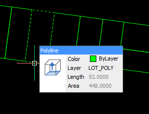
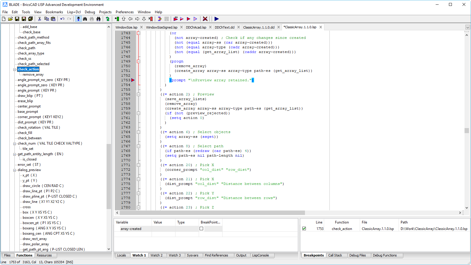
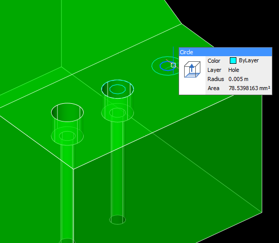
I gave a brief demonstration of (inspector) in the last BricsCAD Unplugged episode about BLADE. However, you don’t need to use BLADE; just enter (inspector) at the command prompt, select an object and you’ll be presented with a dialog like this:
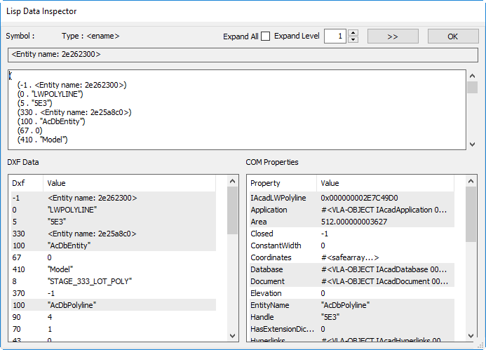
These dialogs are modeless, and you can have as many displayed as you like; you’re not limited to one. This dialog displays the same data in three different ways. At the top, it’s shown in traditional LISP assoc form, and by playing with the Expand controls you can vary the way in which this is pretty-printed. The bottom left pane shows the data in DXF form, which is probably easiest to read if you’re a non-programmer. If you’re more of an ActiveX person or you prefer to see the properties described with words rather than numbers, you’ll prefer the display on the bottom right, which shows the COM properties for the object.
If you want to select another object to inspect without calling (inspector) again, just use the [ > > ] button.
The grayed-out lines indicate data that is considered read-only. It’s important to note that this doesn’t mean it’s impossible to change the data, merely that the ways in which that data can be changed within a program is restricted. Generally, it means you can’t change the ActiveX properties directly, but there are various other means that can be employed in many cases.
The lists are somewhat interactive; double-click on an entity name and you’ll be given another inspector window for that entity. You can burrow down through the drawing database in this way, looking for the source of your mystery DWG problem. If you’re using it while programming, you can use it to work out what set of circumstances is causing your code to trip up in certain drawings.
The (inspector) function has an optional argument, and what it will accept is very flexible. If you pass an entity name to it, you will get the data for that entity displayed. The same principle applies for various ActiveX objects: pass it a layer table object and the appropriate data will be displayed.
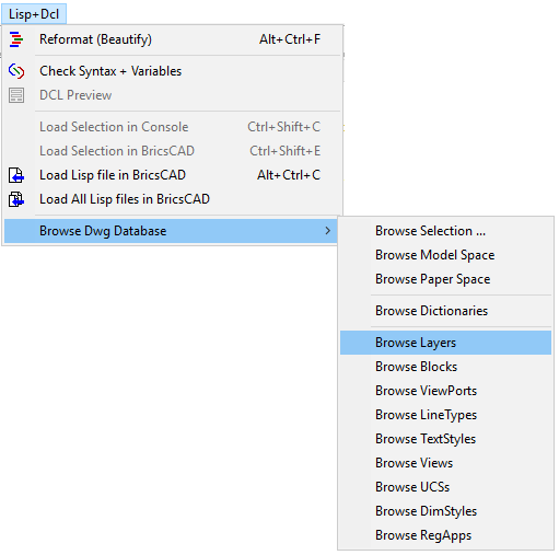
Direct access is provided to various useful things from within BLADE using the pull-down menu Lisp+DCL > Browse DWG Database:
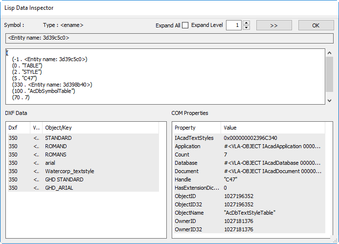
If you pick Browse Text Styles, you’ll see something like this:
Double-click on one of the text style items in the left pane and you will get this:
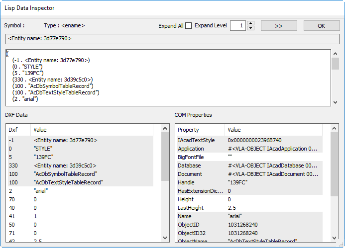
As you can see, this is very handy for tracking down issues both while programming and when diagnosing DWG problems.
Finally, I should note that there is potential for the inspector to provide even more power in future. Bricsys LISP guru Torsten Moses is investigating the possibility of allowing the inspector to modify data, not just inspect it. There’s potential danger there, but if Torsten can make that work safely then that would be another invaluable tool for any DWG-based CAD Manager.
As I stated in my original post, it’s definitely worth a CAD Manager’s while to do the quick download and install of an evaluation BricsCAD. My experience in dealing with Bricsys is that requests for extensions for evaluation purposes are usually accepted, so you probably won’t have to give up your valuable tool as soon as your 30 days are up.

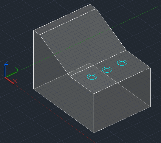
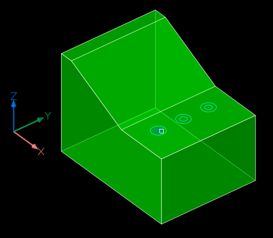

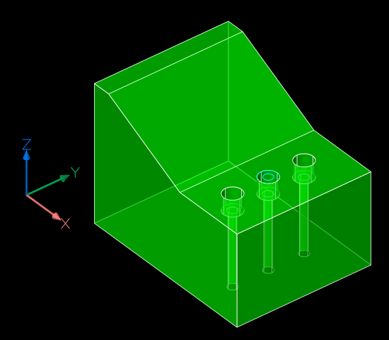
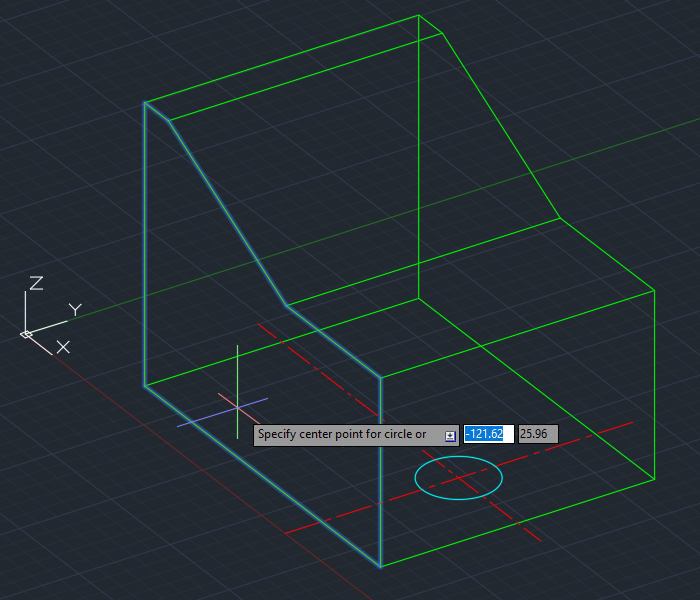
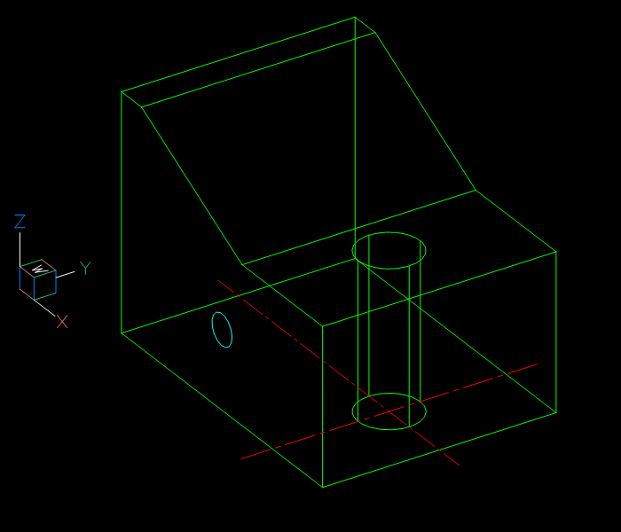
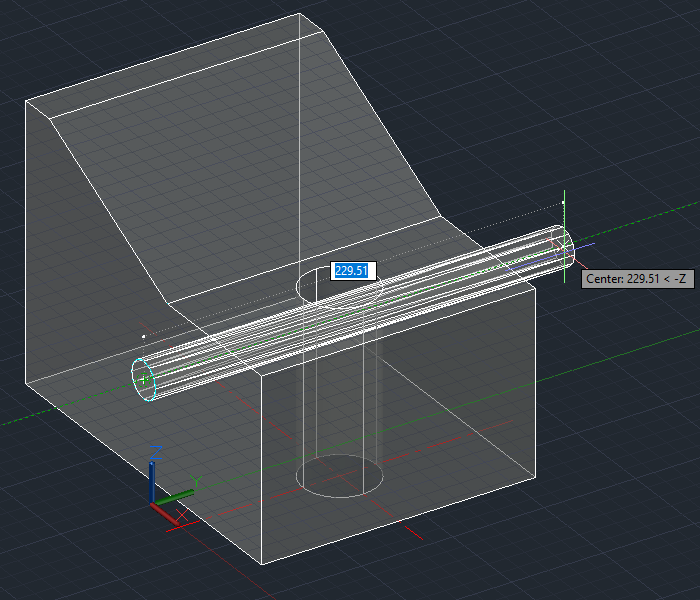
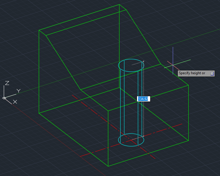
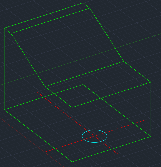
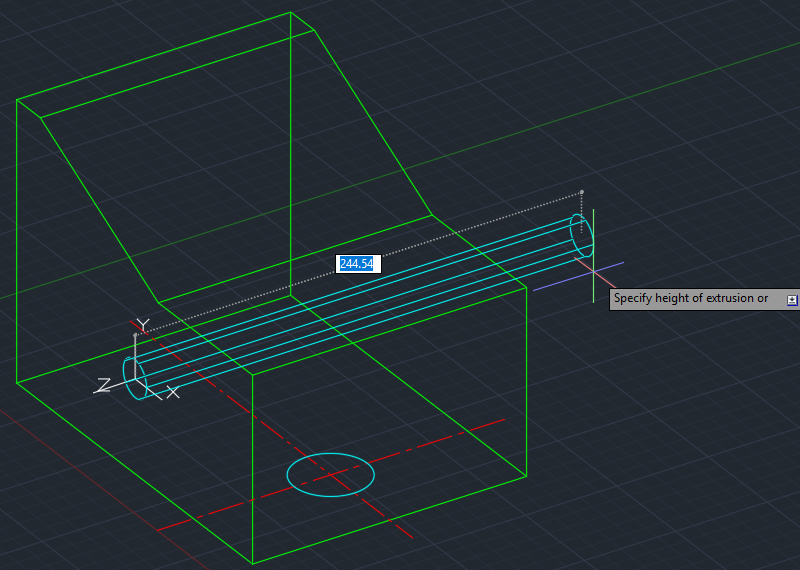
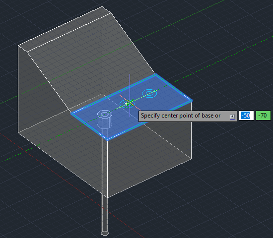
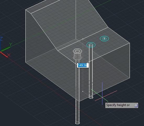
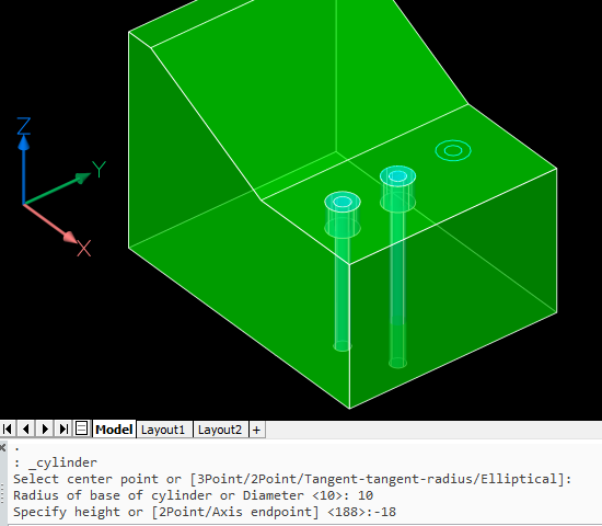
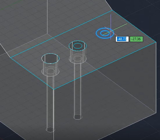
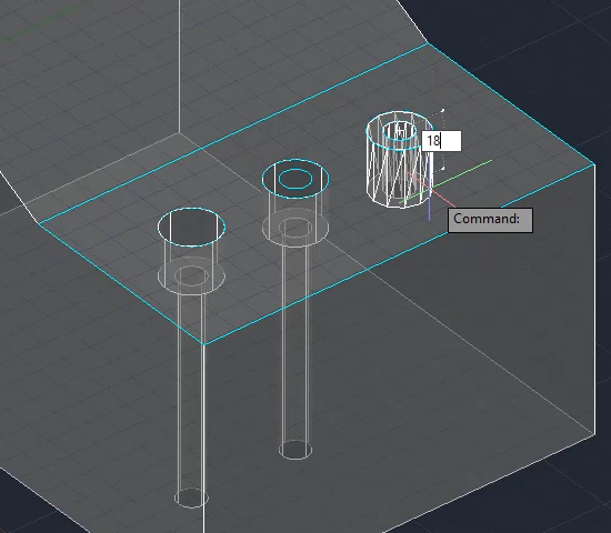
 If you just pick a point as per AutoCAD, the extrusion will go up rather than down. It’s also possible to point to the direction and amount to extrude by using the Direction subcommand and picking two points, for example a top and bottom corner of the solid.
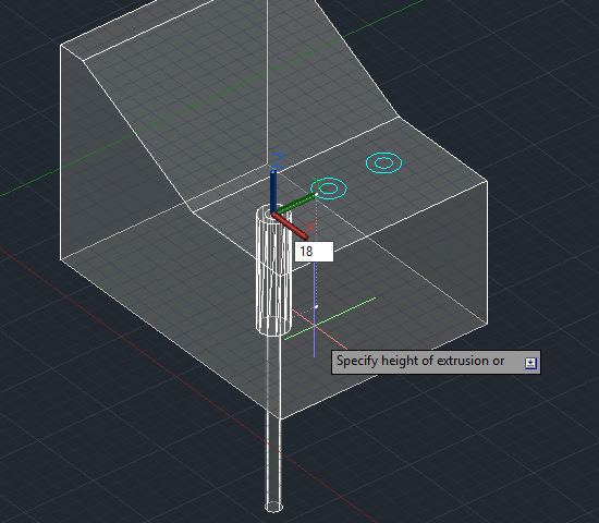
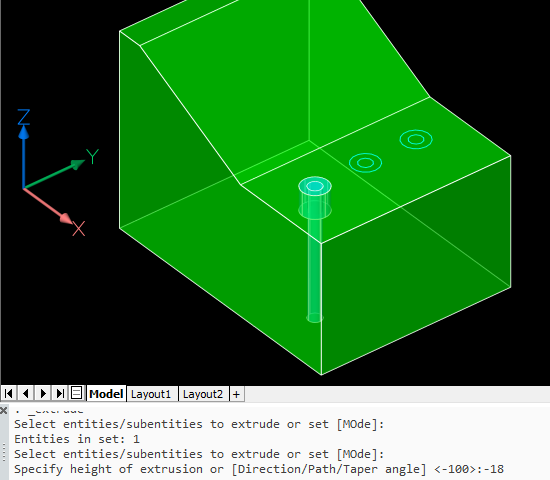
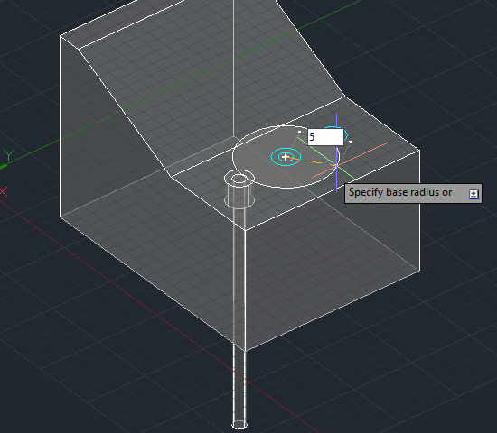
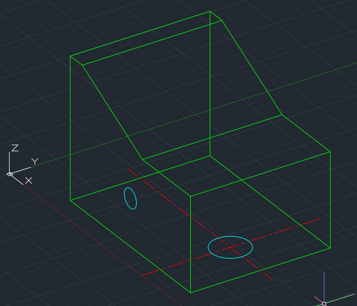
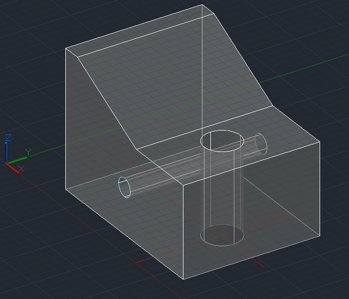
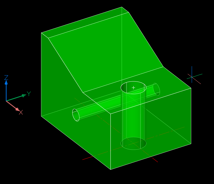
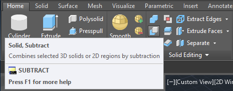
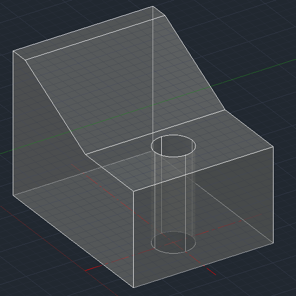
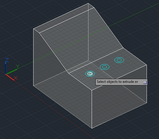
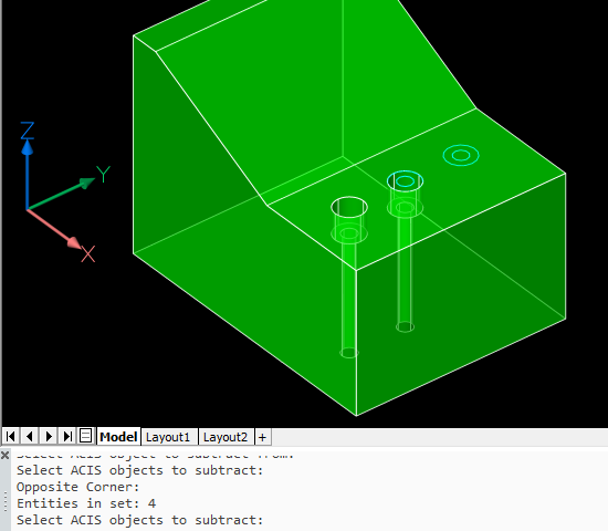
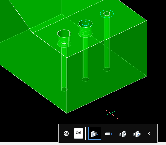
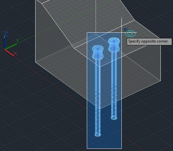 Press Enter to complete that selection and the command.
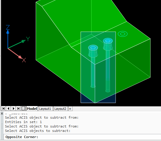 Press Enter to complete that selection and the command.
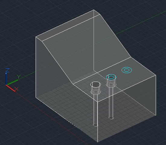
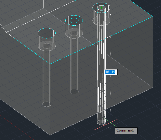

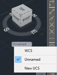
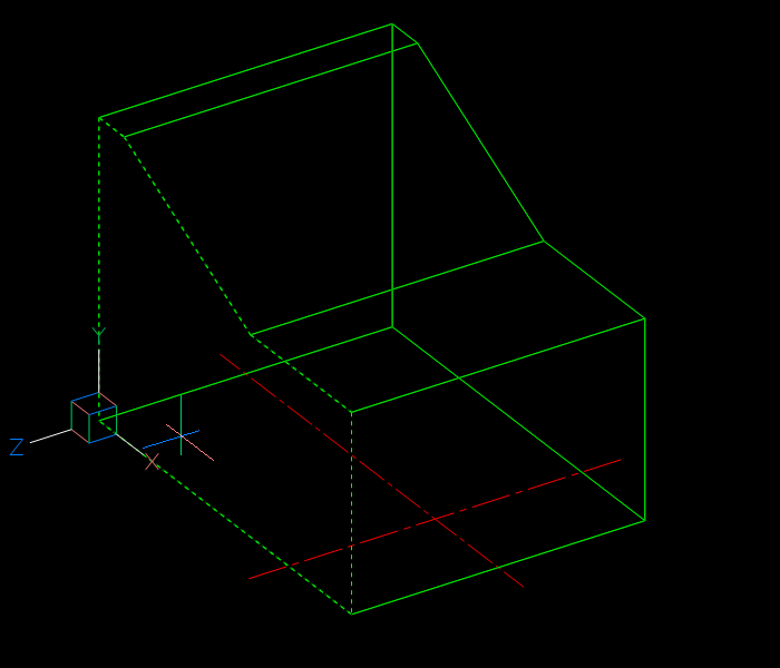
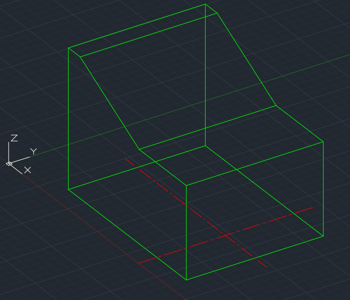
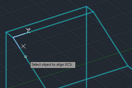
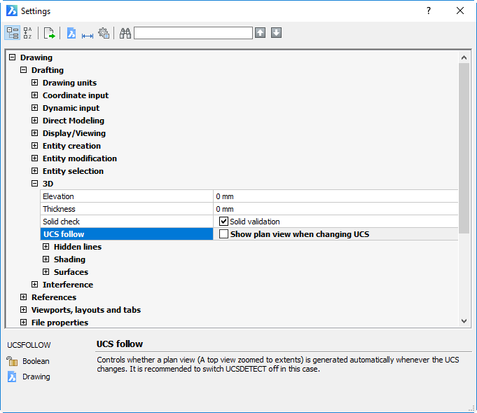
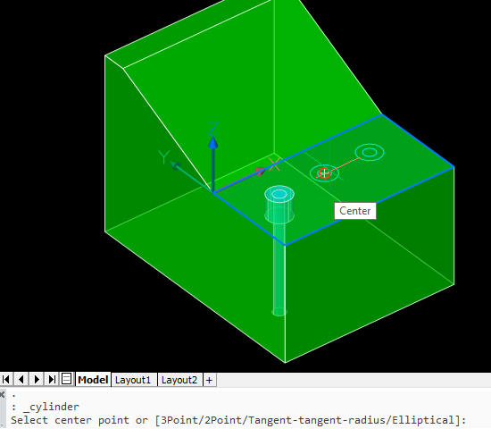
 Note also that your UCS origin is changed by this operation even if dynamic UCS is turned off. To restore it, use UCS Previous or use the UCS menu under the ViewCube to change it to World or any other named UCS: