In this series of posts, I’ll be providing tips that show how to do something in both AutoCAD and BricsCAD, hence A & B.
The Series
The idea behind this series is to provide useful information for several sorts of reader:
- AutoCAD users.
- BricsCAD users.
- People in the process of transitioning from AutoCAD to BricsCAD and who need to know what to do differently (if anything).
- People considering transitioning from AutoCAD to BricsCAD and who want to know about the differences and similarities.
Drilling holes
This post continues to explain more about how to put holes in your 3D models. More than one method involves starting with a planar object (e.g. a circle for a cylindrical hole), but it needs to be in the right spot and in the right plane. The most efficient way of drawing an object in a given plane, where that plane exists on a 3D solid, is to use Dynamic UCS.
Dynamic UCS
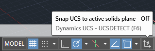
First, we need to make sure Dynamic UCS is turned on. In AutoCAD, the Dynamic UCS icon looks like this:
If that’s not visible, you may need to make it visible using the hamburger menu on the far right of the status bar:
In BricsCAD, the text-based toggle (like the one AutoCAD users have been asking to return ever since it was removed a few releases ago) is DUCS:
![]()
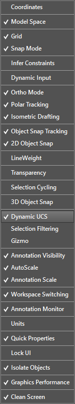
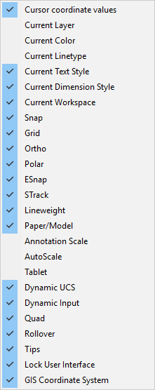
Just in case that toggle’s not visible, there’s a list of toggles in a menu at the bottom right of the BricsCAD user interface, too:
You can also toggle the Dynamic UCS status in both applications using F6.
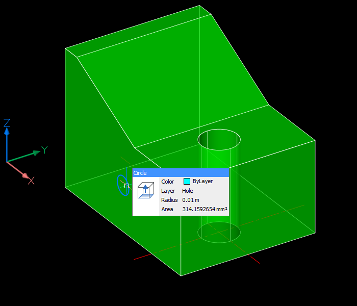
Having established that DUCS is on, invoke the Circle command. Hover over the plane that’s on the left as we’re looking at it, thus:
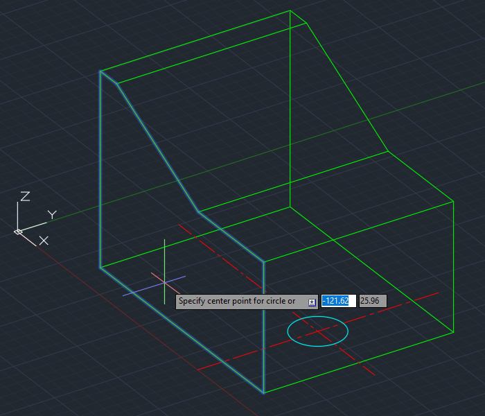
You are now working in a temporary UCS with an origin point in one corner of the 3D solid’s face, and as you move around you can use the coordinate display to get an idea of where the coordinates lie. If I enter -100,50 this is used in relation to the origin of the dynamic UCS and I will get a circle here:
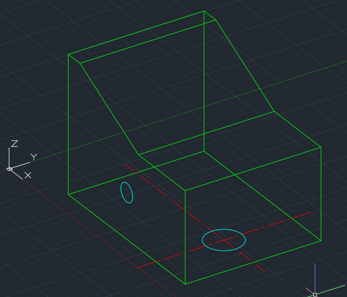
Things work in a similar way in BricsCAD. You don’t get the on-screen dynamic coordinates, but you can still see them in the status bar and you do get a UCS icon that shows you how the temporary UCS is aligned. If you move your cursor around, you will be able to obtain different UCS alignments and easily see where the origin is and which way X and Y are oriented:
With this visual information and the dynamic UCS shown above, you can enter 100,50 to place the circle in the same spot as in AutoCAD.
Now we have our circle (and it could just as easily be a filleted rectangle or any other shape), we could extrude it as described in my previous post. Instead, let’s push and pull it into shape as described below.
Presspulling or Push/pulling
Instead of using the EXTRUDE command, planar objects can be extruded by presspulling them. Before drilling some holes, I should explain that there are several differences (some subtle) between extrusion and presspull:
- Extruding replaces the original objects whereas presspulling leaves them in place and creates new objects.
- The EXTRUDE command expects you to select objects to extrude; the PRESSPULL command allows you to point within an enclosed area. Depending on what you’re starting with, one command will be more suitable than the other.
- Extruding an area enclosed by individual objects (e.g. lines) extrudes the objects into planar surfaces. Presspulling such an enclosed area results in a 3D solid being created based on an extrusion of the enclosed area.
- An EXTRUDE of an enclosed planar object (e.g. circle, closed polyline) creates a 3D object. PRESSPULL can also do this, but when the planar object lies on the surface of a 3D solid, it can also create a hole in that solid.
- Both commands can be used on faces of 3D solids; EXTRUDE will create a new solid based on an extrusion of that face and PRESSPULL will modify the original solid.
Presspulling in AutoCAD
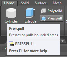
In AutoCAD, you can use the PRESSPULL command:
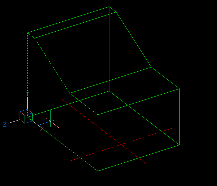
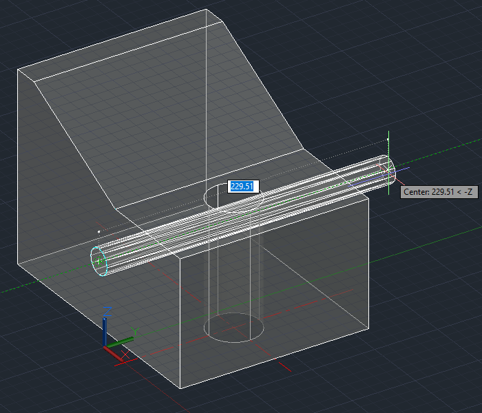
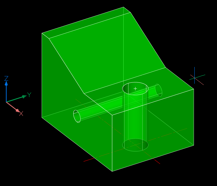
Alternatively, you can use Ctrl+Shift+E to invoke presspulling: hold all three keys down and point within an enclosed area. Here’s an example. A circle has been drawn on the left vertical surface of our solid. Hold down Ctrl+Shift+E together and pick the interior of the circle. Let go of the keys and move your mouse to the right:
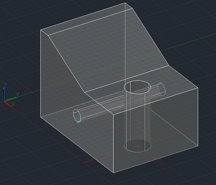
Pick a point beyond the extents of the solid. A hole is automatically created in the solid without having to explicitly subtract it, thus:
User actions required: a three-key combination and two picks. Note that the original circle is still present and if you don’t want it there you will need to erase it.
Push/Pulling in BricsCAD
In BricsCAD, there is no PRESSPULL command. Instead, the closest equivalent command name is DMPUSHPULL (the DM stands for Direct Modeling).
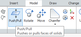
This command expects to work on faces of 3D solids, which is not exactly what we’re after for drilling holes. Instead, we use the DMEXTRUDE command. Now it might seem confusing that there are different commands to use for similar things, but in practice that doesn’t matter. That’s because we can just use the Quad Cursor and really not care what the underlying command is called. If you hover over a 3D solid’s face, the Quad Cursor gives you the options you need for dealing with that, and if you hover over a circle you are given the appropriate options for that instead.
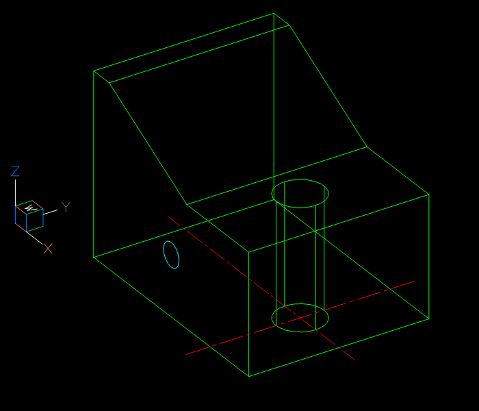
Here’s the same example as above, this time done in BricsCAD. Hover over an object that defines an enclosed area, in this case our circle:
The Quad Cursor uses AI technology to initially provide the option that it thinks you’re most likely to use with that object under the current circumstances. I find it’s remarkably good at guessing what you want to do. If it’s wrong, you can get at a whole bunch of other options with a bit more hovering, but in this case it’s right; we do want to extrude the circle. Pick that icon, move over to the right and pick. That will create the hole:
User actions required: a hover and two picks. Again, the original circle remains behind and will need to be erased if you don’t want it left hanging around.
What about more complex holes? There are more tips and tricks coming, so watch this space.
There seem to be a few other system vars needing to be set right for quad cursor to show right. I think its ROLLOVERTIPS to 1, but I still don’t see an action suggested. I started reading the help, and wow there are a lot of quad settings. I’ve heard a lot about the quad, and am typically not a fan of pop-up GUI things I have to wait for and click with the mouse, but still want to see it work. I think a post on what is needed to get the quad to work, assuming everything was set wrong, is needed. Also, I have to say the bcad options dialog is hard to use. I was looking for the tooltips item and searching tooltips did not help. I don’t have the hang of it yet.
I’m just using the default BricsCAD settings. You’re probably aware that I’ve never been a fan of stuff getting in my face either and was expecting to hate the Quad, but I gave it a chance and it won me over. I also much prefer the BricsCAD options dialog, but each to his own.