Category Archives: 3D

A & B Tip 9 – drilling holes 3 – counterbores

In this series of posts, I’ll be providing tips that show how to do something in both AutoCAD and BricsCAD, hence A & B.

The Series

The idea behind this series is to provide useful information for several sorts of reader:

  1. AutoCAD users.
  2. BricsCAD users.
  3. People in the process of transitioning from AutoCAD to BricsCAD and who need to know what to do differently (if anything).
  4. People considering transitioning from AutoCAD to BricsCAD and who want to know about the differences and similarities.

Counterbored holes

This post continues to explain more about how to put holes in your 3D models. In this post I’ll be describing how to construct counterbored holes. Hint: the most efficient method is described last.

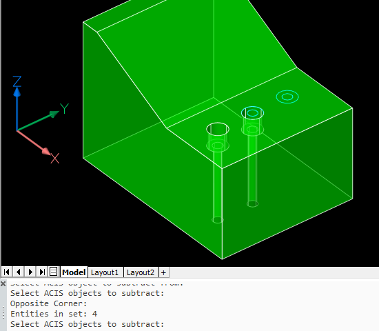
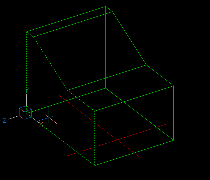
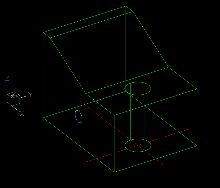
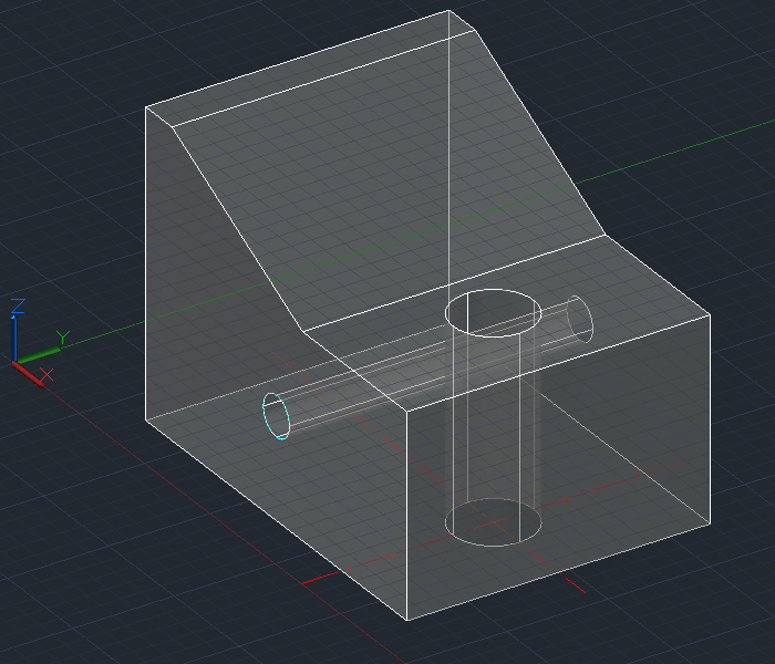
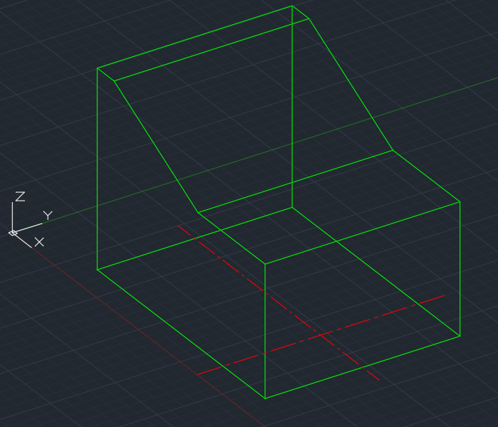
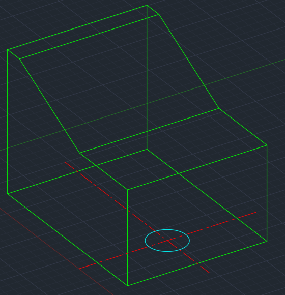
I’m going to start with this model and use different methods to create three counterbored diameter 10 holes that go through the block, each with a diameter 20 x 18 deep counterbore. I’ve placed circles of diameter 10 and 20 in place to indicate where the holes are going to go, and in some cases to act as the basis for extrusion.
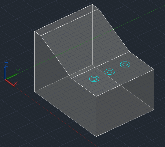
If you’re unsure about how to locate these circles in exactly the right spots in 3D space, see my earlier drilling holes posts, part 1 and part 2.

Extruding circles

Assuming we have appropriate circles to work with, we can extrude them to create cylinders, then subtract them. This works in basically the same in both AutoCAD and BricsCAD, but there are differences:

AutoCAD BricsCAD
Invoke the EXTRUDE command:
Select the inner circle and press Enter to complete the selection process:
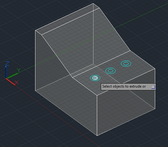
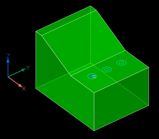
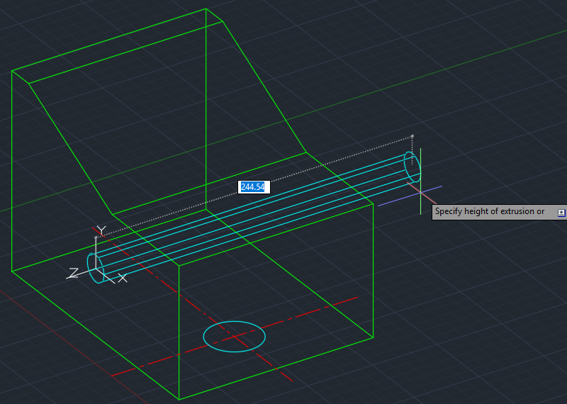
Move your cursor down and click when the extrusion goes beyond the bottom of the block:
Enter a negative number that equals or exceeds 100 (the thickness of the block):
If you just pick a point as per AutoCAD, the extrusion will go up rather than down. It’s also possible to point to the direction and amount to extrude by using the Direction subcommand and picking two points, for example a top and bottom corner of the solid.
Repeat the above process for the second circle, but this time specify an extrusion height of 18 while the cursor is located such that the extrusion is going down rather than up:
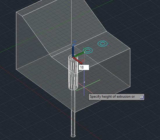
Repeat the above process for the second circle, but this time specify an extrusion height of -18. It has to be negative, otherwise the extrusion will go up even if you’re pointing down (unlike AutoCAD).
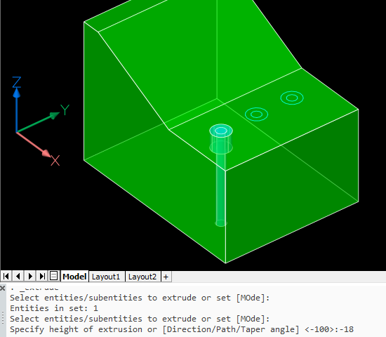
We’ll subtract these cylinders later.

Drawing cylinders

You can draw cylinders to subtract without needing construction circles. In this case one of the circles is just used to help locate the cylinder center point, but you can use other methods that involve no construction geometry instead, as explained in my first drilling holes post.

AutoCAD BricsCAD
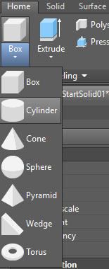
Invoke the CYLINDER command (Solid, not Surface):
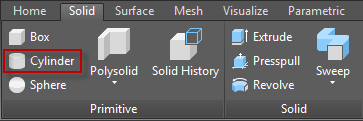
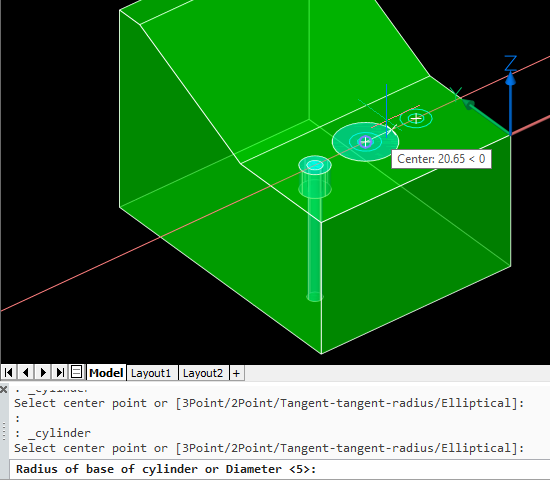
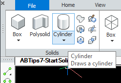
Invoke the CYLINDER command (Solids, not Meshes):
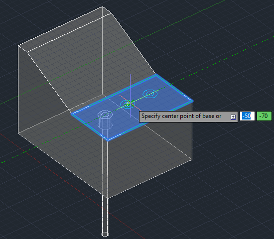
Locate the center of the cylinder, in this case using the center object snap:
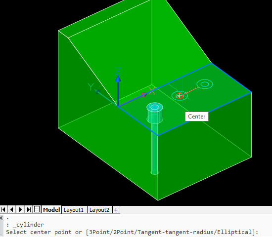
Locate the center of the cylinder, in this case using the center entity snap:
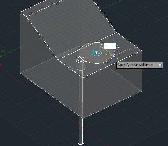
Enter a radius of 5:
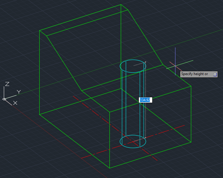
Move your cursor down and click when the extrusion goes beyond the bottom of the block:
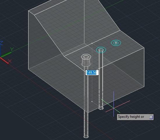
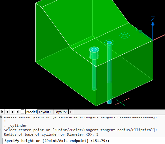
Repeat the above process for the second cylinder, but this time specify a height of 18 while the cursor is located such that the extrusion is going down rather than up:
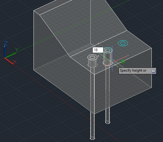
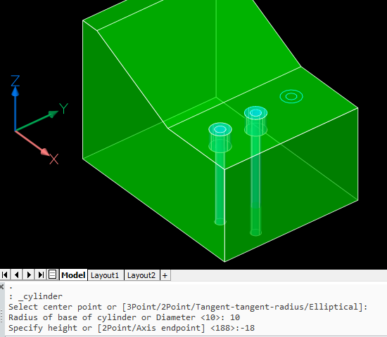
Repeat the above process for the second cylinder, but this time specify a height of -18:
Subtracting the cylinders

We can subtract all four cylinders at once to create two of the counterbored holes. This process is the same in both applications.

AutoCAD BricsCAD
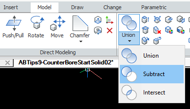
Invoke the SUBTRACT command:
Select the main solid as the object to subtract from and press Enter to complete that selection. Then select the cylinders to remove. This is easiest with an implied window. Pick a corner point containing no objects, starting on the left. Then pick the opposite corner to the right.
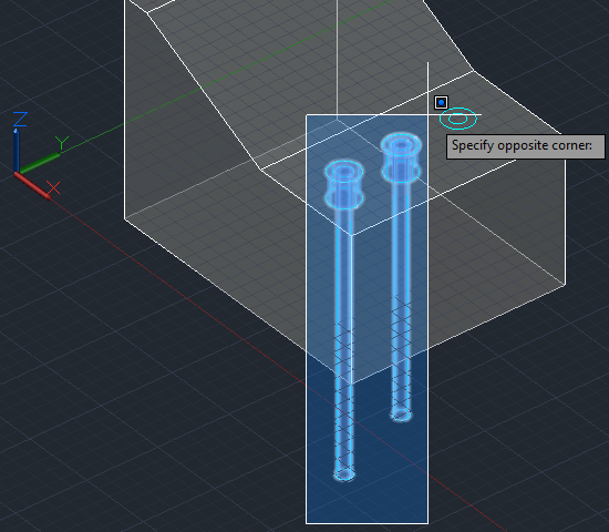
Press Enter to complete that selection and the command.
Select the main solid as the object to subtract from and press Enter to complete that selection. Then select the cylinders to remove. This is easiest with an implied window. Pick a corner point containing no objects, starting on the left. Then pick the opposite corner to the right.
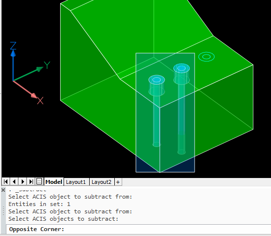
Press Enter to complete that selection and the command.
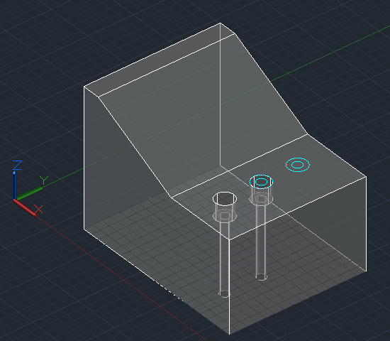
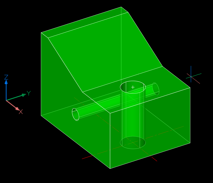
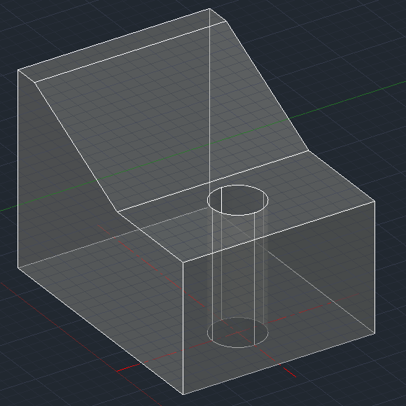
End result:
End result:

Note that the first method replaces the circles with cylinders. The second method only uses the circles to help locate the center; they don’t really need to be there at all and are ignored.

Presspulling or Push/pulling

As described before, planar objects such as circles can be extruded by presspulling them. We’ll use that method to create the third counterbored hole. In this case, the operations differ somewhat between AutoCAD and BricsCAD.

AutoCAD BricsCAD
Hold down Ctrl+Shift+E to turn on dynamic presspull mode, hover over the space between the two circles and pick:
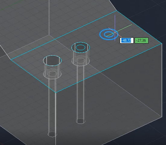
Hover over the inner circle. You should see the Quad Cursor appear, suggesting a push/pull operation. Pick the icon to accept that operation:
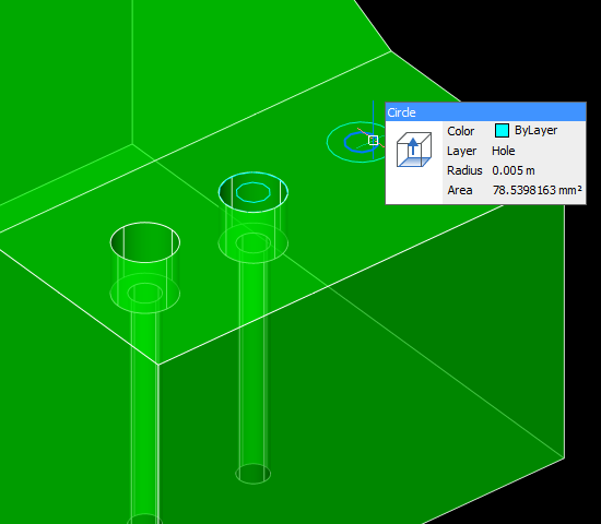
Now you can release Ctrl_Shift+E. Move your cursor down and enter 18:
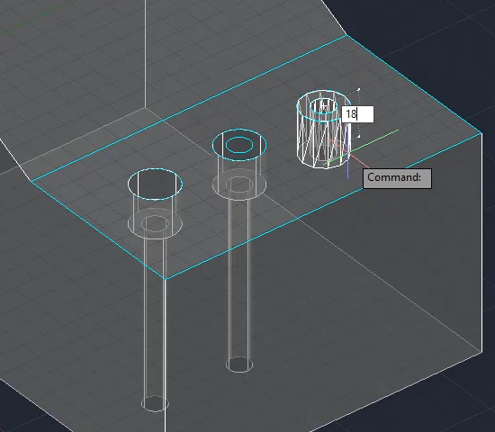
Move your cursor down beyond the bottom of the block and pick.
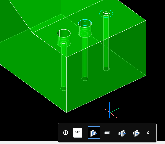
Note the on-screen reminder that you can hit the Ctrl key to switch between several different types of push/pull operations. We can ignore this because in this case we want to use the default. However, it’s worth noting that this feature exists because it’s very handy.
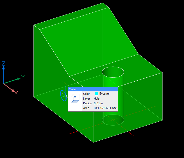
Hold down Ctrl+Shift+E to turn on dynamic presspull mode, hover over the inside of the inner circle and pick. Release Ctrl+Shift+E, move your cursor down beyond the bottom of the block and pick:
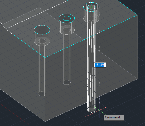
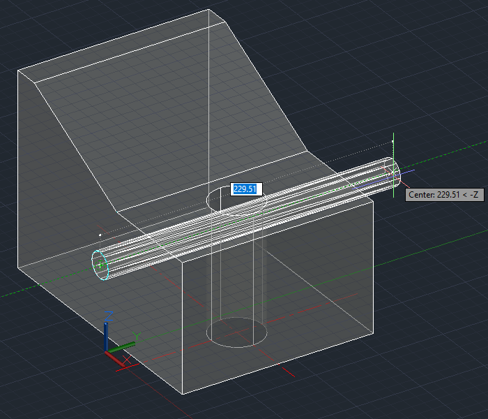
Hover over the outer circle and pick the push/pull icon on the Quad Cursor. You could enter a height of -18, but in this case there’s a handy nearby hole counterbored to the correct depth and we can just pick the center of that instead:
In the AutoCAD presspull end result, the circles are left behind so if you don’t want them you will need to erase them.
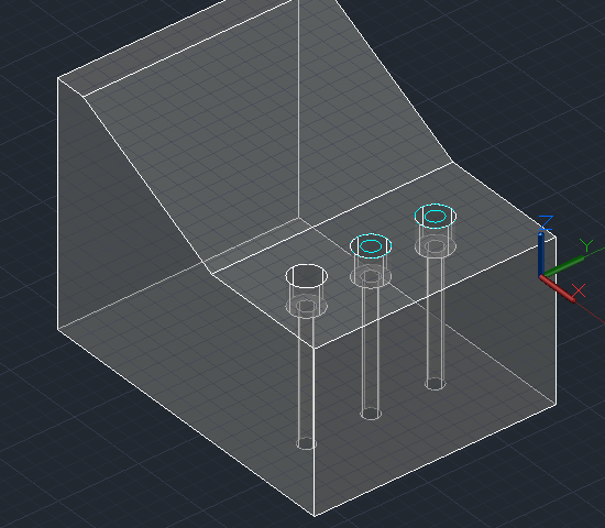
Note also that your UCS origin is changed by this operation even if dynamic UCS is turned off. To restore it, use UCS Previous or use the UCS menu under the ViewCube to change it to World or any other named UCS:
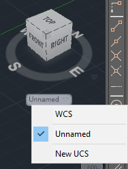
In the BricsCAD push/pull end result, the circles are converted to holes so no more action is required. No UCS restoration is necessary.
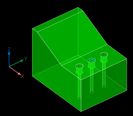
Summary

Assuming you have construction circles in place, presspulling is the most efficient of the three methods in AutoCAD, even allowing for the tidy-up required at the end.

BricsCAD’s Quad-based push/pull operation is the most efficient method of the lot. Hover, pick, pick and hover, pick, pick is enough to create a counterbored hole.

Next: countersunk holes.

Autodesk Fusion 360 massive subscription price rise/drop

Autodesk’s cloud-based 3D design tool, Fusion 360, is changing price and structure from 7 October 2018. Whether it’s a huge price rise or a huge price drop depends on your perspective.

Price rise

The current annual subscription cost for Fusion 360 is US$310 and that’s going to change to US$495, which represents a 60% price increase. Existing subscribers are being kept at the same annual rate of US$310 or US$300 (depending on when you first subscribed) “for as long as you renew”. Existing subscribers, that looks like a promise to never increase your prices as long as you keep up the payments. Make sure you capture and retain all of Autodesk’s statements on this matter, in case that promise eventually gets forgotten.

However, for that amount you’ll now be getting the same features that are currently in Fusion 360 Ultimate; the lesser and greater versions are being amalgamated and just called Fusion 360.

Price drop

The current annual subscription cost for Fusion 360 Ultimate is US$1535. As that’s going to change to US$495, that represents a 68% price drop.

Is it fair?

If you currently use Fusion 360, even if you have no use for Advanced Simulation, Advanced Manufacturing or Generative Design, it’s not bad news. The only downside is that you’ll now be paying more if you need to add seats, or if you temporarily drop and resume subscription.

If you currently use Fusion 360 Ultimate, you are probably going to be overjoyed at spending a lot less in future. If you just paid US$3,070.00 for a 2-year subscription that’s about to be worth US$990, you might be less pleased. To assuage your ire, Autodesk will be giving you (and all existing annual subscribers) another 24 months subscription, gratis. Still, depending on the term length and renewal timing, some customers are going to be much luckier than others. That might annoy the less fortunate.

I think Autodesk has been very fair and reasonable with the way it has handled these changes. However, it does serve as a reminder that once you’re a subscriber, you’re at the mercy of your software company.

A & B Tip 8 – drilling holes 2

In this series of posts, I’ll be providing tips that show how to do something in both AutoCAD and BricsCAD, hence A & B.

The Series

The idea behind this series is to provide useful information for several sorts of reader:

  1. AutoCAD users.
  2. BricsCAD users.
  3. People in the process of transitioning from AutoCAD to BricsCAD and who need to know what to do differently (if anything).
  4. People considering transitioning from AutoCAD to BricsCAD and who want to know about the differences and similarities.

Drilling holes

This post continues to explain more about how to put holes in your 3D models. More than one method involves starting with a planar object (e.g. a circle for a cylindrical hole), but it needs to be in the right spot and in the right plane. The most efficient way of drawing an object in a given plane, where that plane exists on a 3D solid, is to use Dynamic UCS.

Dynamic UCS

First, we need to make sure Dynamic UCS is turned on. In AutoCAD, the Dynamic UCS icon looks like this:

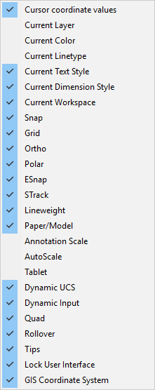
If that’s not visible, you may need to make it visible using the hamburger menu on the far right of the status bar:

In BricsCAD, the text-based toggle (like the one AutoCAD users have been asking to return ever since it was removed a few releases ago) is DUCS:

Just in case that toggle’s not visible, there’s a list of toggles in a menu at the bottom right of the BricsCAD user interface, too:

You can also toggle the Dynamic UCS status in both applications using F6.

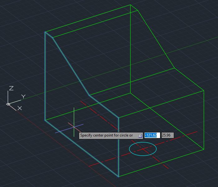
Having established that DUCS is on, invoke the Circle command. Hover over the plane that’s on the left as we’re looking at it, thus:

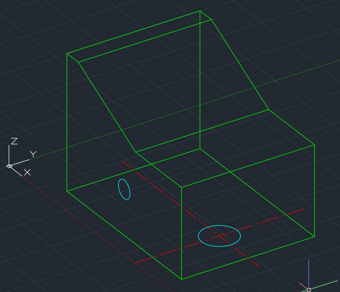
You are now working in a temporary UCS with an origin point in one corner of the 3D solid’s face, and as you move around you can use the coordinate display to get an idea of where the coordinates lie. If I enter -100,50 this is used in relation to the origin of the dynamic UCS and I will get a circle here:

Things work in a similar way in BricsCAD. You don’t get the on-screen dynamic coordinates, but you can still see them in the status bar and you do get a UCS icon that shows you how the temporary UCS is aligned. If you move your cursor around, you will be able to obtain different UCS alignments and easily see where the origin is and which way X and Y are oriented:

With this visual information and the dynamic UCS shown above, you can enter 100,50 to place the circle in the same spot as in AutoCAD.

Now we have our circle (and it could just as easily be a filleted rectangle or any other shape), we could extrude it as described in my previous post. Instead, let’s push and pull it into shape as described below.

Presspulling or Push/pulling

Instead of using the EXTRUDE command, planar objects can be extruded by presspulling them. Before drilling some holes, I should explain that there are several differences (some subtle) between extrusion and presspull:

  • Extruding replaces the original objects whereas presspulling leaves them in place and creates new objects.
  • The EXTRUDE command expects you to select objects to extrude; the PRESSPULL command allows you to point within an enclosed area. Depending on what you’re starting with, one command will be more suitable than the other.
  • Extruding an area enclosed by individual objects (e.g. lines) extrudes the objects into planar surfaces. Presspulling such an enclosed area results in a 3D solid being created based on an extrusion of the enclosed area.
  • An EXTRUDE of an enclosed planar object (e.g. circle, closed polyline) creates a 3D object. PRESSPULL can also do this, but when the planar object lies on the surface of a 3D solid, it can also create a hole in that solid.
  • Both commands can be used on faces of 3D solids; EXTRUDE will create a new solid based on an extrusion of that face and PRESSPULL will modify the original solid.

Presspulling in AutoCAD

In AutoCAD, you can use the PRESSPULL command:

Alternatively, you can use Ctrl+Shift+E to invoke presspulling: hold all three keys down and point within an enclosed area. Here’s an example. A circle has been drawn on the left vertical surface of our solid. Hold down Ctrl+Shift+E together and pick the interior of the circle. Let go of the keys and move your mouse to the right:

Pick a point beyond the extents of the solid. A hole is automatically created in the solid without having to explicitly subtract it, thus:

User actions required: a three-key combination and two picks. Note that the original circle is still present and if you don’t want it there you will need to erase it.

Push/Pulling in BricsCAD

In BricsCAD, there is no PRESSPULL command. Instead, the closest equivalent command name is DMPUSHPULL (the DM stands for Direct Modeling).

This command expects to work on faces of 3D solids, which is not exactly what we’re after for drilling holes. Instead, we use the DMEXTRUDE command. Now it might seem confusing that there are different commands to use for similar things, but in practice that doesn’t matter. That’s because we can just use the Quad Cursor and really not care what the underlying command is called. If you hover over a 3D solid’s face, the Quad Cursor gives you the options you need for dealing with that, and if you hover over a circle you are given the appropriate options for that instead.
Here’s the same example as above, this time done in BricsCAD. Hover over an object that defines an enclosed area, in this case our circle:

The Quad Cursor uses AI technology to initially provide the option that it thinks you’re most likely to use with that object under the current circumstances. I find it’s remarkably good at guessing what you want to do. If it’s wrong, you can get at a whole bunch of other options with a bit more hovering, but in this case it’s right; we do want to extrude the circle. Pick that icon, move over to the right and pick. That will create the hole:

User actions required: a hover and two picks. Again, the original circle remains behind and will need to be erased if you don’t want it left hanging around.

What about more complex holes? There are more tips and tricks coming, so watch this space.

A & B Tip 7 – drilling holes 1

In this series of posts, I’ll be providing tips that show how to do something in both AutoCAD and BricsCAD, hence A & B.

The Series

The idea behind this series is to provide useful information for several sorts of reader:

  1. AutoCAD users.
  2. BricsCAD users.
  3. People in the process of transitioning from AutoCAD to BricsCAD and who need to know what to do differently (if anything).
  4. People considering transitioning from AutoCAD to BricsCAD and who want to know about the differences and similarities.

Drilling holes

This post explains how to put holes in your 3D models. This post will cover some fairly straightforward topics but I intend to cover more involved details in future posts. I’ll assume you have a basic understanding of creating 3D primitives and the boolean operations (union, subtract and intersect). I will be using the 3D Modeling workspace in both AutoCAD and BricsCAD. I’m going to start with the dynamic UCS feature turned off and the 2D Wireframe visual style.

Vertical cylinder subtraction

Let’s take the simplest case. You have a solid and you just want to place a cylindrical hole in a known location that you already have geometry you can snap to. For example, you want to drill a DIA 40 hole right through this part, using the centerlines shown:

Start with the CYLINDER command:

AutoCAD BricsCAD

Pick the intersection of the two centerlines, enter a radius of 20 and a height of 100. You don’t have to be precise with the height, you can just point to any height that’s over 100:

To create the hole, use the SUBTRACT command:

AutoCAD BricsCAD

With this command it’s important to select the objects in the right order. Select the object(s) you’re substantiating from first, then press Enter to finish the selection process for those objects. Then select the object(s) you’re subtracting and press Enter to finish that selection process. That will give you your hole (temporarily switched to X-Ray visual style for clarity):

Extruding a circle

Instead of creating the cylinder diectly, you can instead extract a circle. This is an extra step if you don’t already have a circle of the right size in the right place, but less work if you do. For example, if you’re converting a 2D drawing to a 3D model, you’ll probably have the circle already.

Invoke the EXTRUDE command:

AutoCAD BricsCAD

Select the circle, press Enter to finish the selection (because you can extrude several objects at once) and specify a height of at least 100, as with the CYLINDER command. Subtract the resultant cylinder and you’re done.

It’s important to note that extrusions work perpendicular to the plane of the object(s) being extruded. In this case the cylinder is created vertically because the circle lies flat (in terms of the World Coordinate System). If you have a circle lying in a different plane, the extrusion will be perpendicular to that plane. For example, here a circle that lies in a vertical plane is being extruded horizontally:

Drawing a circle in the other planes

That’s all well and good if you have a circle in the right plane, but what if you need to draw one? You have several alternatives.

One method is to draw your circle in whatever plane you like, then use the ALIGN command to move it into place. That works, but it’s not that efficient.

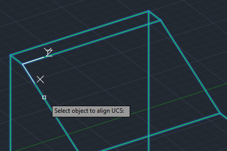
Alternatively, you can change your UCS to align with your desired plane, and then just draw your circle. That can be fiddly, but if you have a handy solid object containing the plane you want to draw in, you can use the UCS command’s OBject option (hot tip: E for Entity does the same thing). By carefully hovering over the plane, you can set up your desired UCS with one click and a lot less tiresome fiddling around than trying to work out what the other (somewhat arcane) options of the UCS command all mean. Here, the UCS command’s OBject option is shown in action:

Note that this is an example of one of the very few things that works in AutoCAD but not BricsCAD. The UCS command’s OBject (and Entity) option exists, but you can’t use it to align a UCS with a solid’s face. You can, however, use the UCS command’s Face option. That exists in both applications, but I prefer the way it works in BricsCAD where the origin of the UCS is placed in one corner of the face with no further interaction required. In AutoCAD, the default is to place the UCS origin at some random point you used to select the face so if you need to locate points precisely there is a bit more messing around required.

Upshot: Use UCS E in AutoCAD and UCS F in BricsCAD.

In any case, there are other, more efficient ways to skin this particular cat. In my view, the most efficient way of drawing an object in a given plane, where that plane exists on a 3D solid, is to use Dynamic UCS. I’ll explain that, and how to push and pull your holes into submission, in the next post.

A & B Tip 5 – polyline areas

In this series of posts, I’ll be providing tips that show how to do something in both AutoCAD and BricsCAD, hence A & B.

The Series

The idea behind this series is to provide useful information for several sorts of reader:

  1. AutoCAD users.
  2. BricsCAD users.
  3. People in the process of transitioning from AutoCAD to BricsCAD and who need to know what to do differently (if anything).
  4. People considering transitioning from AutoCAD to BricsCAD and who want to know about the differences and similarities.

What area is that polyline?

There are several ways of determining the area enclosed by a polyline. This post goes through the various methods. You will also notice that in each of the methods, you get the length (perimeter) as a bonus.

Spoiler alert: the most efficient methods are at the bottom. There’s a one-click method in AutoCAD (it needs a little setting up first) and a zero-click method in BricsCAD.

LIST command in AutoCAD

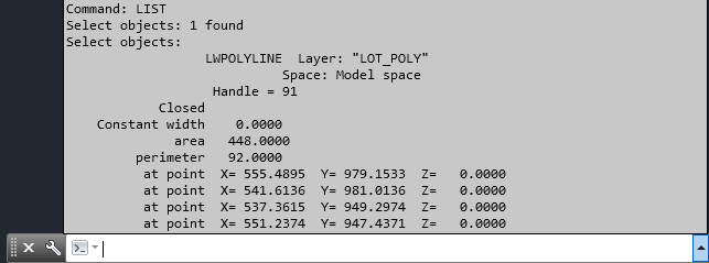
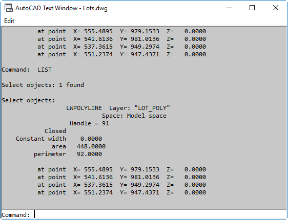
The oldest method is the good old LIST command. Although this has been around for ever, here’s how it works in recent AutoCAD releases. Issue the LIST command, select the polyline, press Enter to finish the selection, and above your floating command line AutoCAD will show something like this:

If this display goes away and you want to see it again, hit F2 and it will return. If you have a docked command line, AutoCAD will display the information on the text screen, which it will then display:

If you have a floating command line but want to see the text screen rather than the over-the-command-line popup, you can switch to it using Ctrl+F2.

LIST command in BricsCAD

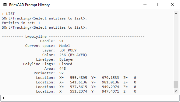
The command works in just the same way in BricsCAD as it does in AutoCAD with the docked command line.. The main differences are that the BricsCAD default interface has a docked command line, and that the text screen (called Prompt History in BricsCAD) is displayed even when using a floating command line.

If the text screen goes away or is obscured, you can restore it using the familiar-to-AutoCAD-oldtimers keystroke of F2 (not Ctrl+F2, which toggles the ribbon in BricsCAD).

Unit precision in BricsCAD

Another difference you might notice is that the only whole units are displayed. This is because BricsCAD respects the setting of DIMZIN when displaying values in the AREA command and AutoCAD doesn’t. In this drawing, DIMZIN is set to 8, which suppresses trailing zeroes. Because the area is exactly 448.0, BricsCAD displays it as 448. If DIMZIN is not set to suppress trailing zeroes, this doesn’t happen. If DIMZIN is set to 0, BricsCAD displays the area using the setting for linear units precision, LUPREC. If this is 4, the LIST command will display the area as 448.0000, as it does in AutoCAD.

This respect for DIMZIN applies in other places in BricsCAD too. For the remainder of this post I’ll have DIMZIN set to 0.

AREA command in AutoCAD

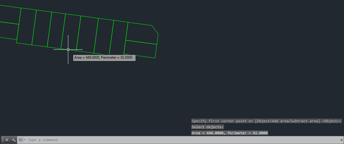
Another good old method is the AREA command. Issue the command, use the Object option and pick your polyline. You will be shown the area in two places as shown here:

AREA command in BricsCAD

The AREA command works similarly in BricsCAD. Although the options displayed indicate that the subcommand is Entity rather than Object, you can in fact use either E or O to initiate selection of an object. Unlike AutoCAD, the area is displayed in one place only, the command prompt area:

Note that the AREA command in both applications gives you more options, including adding together several areas.

Properties palette in AutoCAD

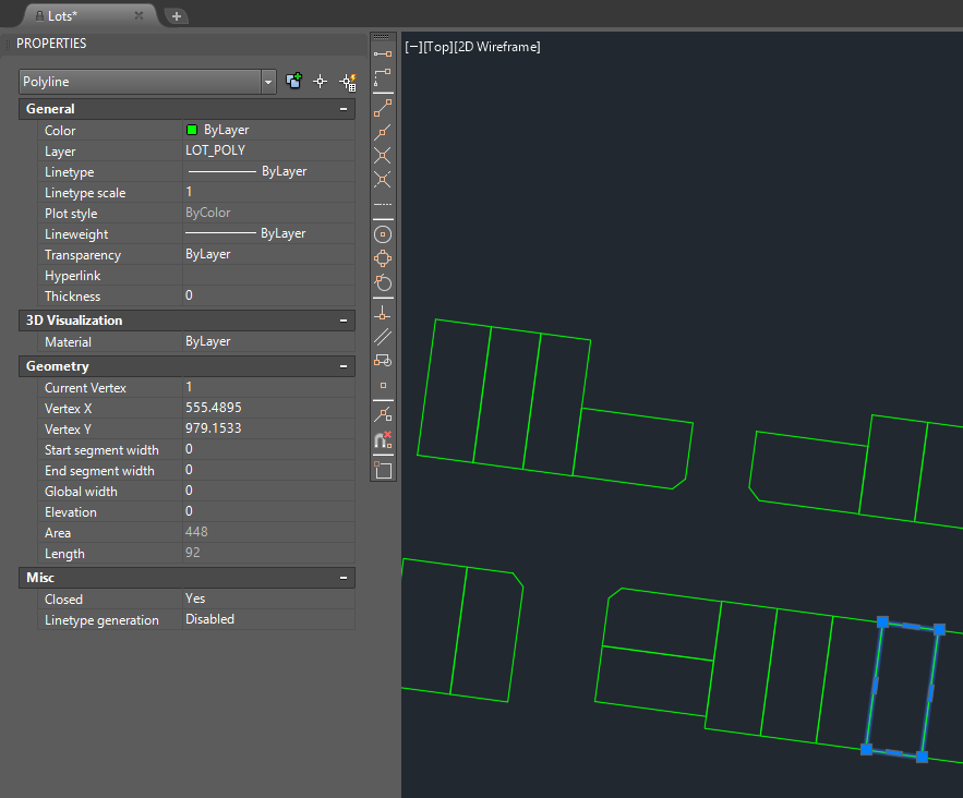
If you have the Properties palette visible (Ctrl+1 will toggle it on), you can simply select the polyline and the area will be displayed in the palette, thus:

Note that unlike the AutoCAD AREA command, the Properties palette does respect the value of DIMZIN. To display the trailing zeroes, first set DIMZIN to 0.

Properties palette in BricsAD

Using the Properties palette in BricsCAD is identical to AutoCAD. Here’s the display:

Quick Properties in AutoCAD

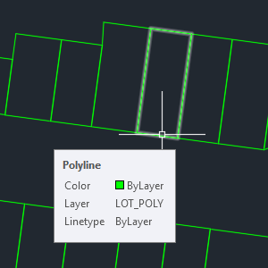
Quick Properties is a cursor-based cut-down version of the Properties palette. It’s not what you get when hovering, which is this:

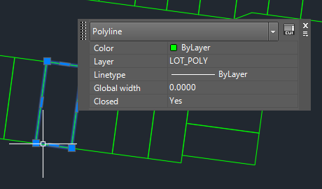
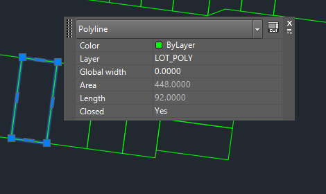
What you want is Quick Properties, which you only get when you select an object, for example:

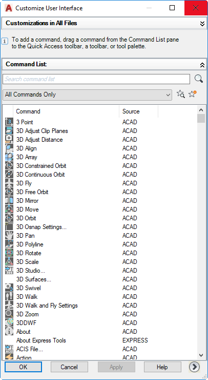
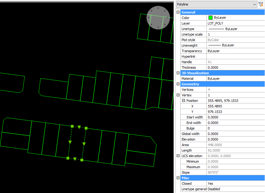
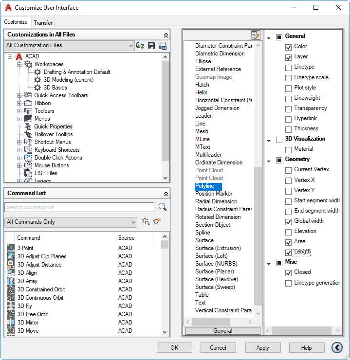
Unfortunately, Area is missing. It was there once upon a time, but there were performance problems so it was removed by default. However, you can add it back in. Invoke CUI and pick Quick Properties on the left. Scroll down on the right and pick Polyline.

Turn on Area (and Length if you want). Pick OK. Now see what happens when you select a polyline:

Note: in AutoCAD 2014 (and maybe others), the Area option was missing. There’s a workaround, but it’s a complex hack and well beyond the scope of this post.

Quad cursor in BricsCAD

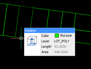
The easiest way to find a polyline area in BricsCAD is just to hover over it. The Quad cursor will appear, giving you the information you need:

Alternatives

If you’re doing this regularly, it makes sense to automate it as much as possible. Depending what you want, menu macros might help. There are also various free LISP routines around that do this sort of thing, for example these by Lee Mac. If you have more specific requirements (e.g. automatic area label, export to CSV), then that’s the sort of thing I do for a living so feel free to get in touch.

A & B Tip 4 – turning on toolbars

In this series of posts, I’ll be providing tips that show how to do something in both AutoCAD and BricsCAD, hence A & B.

The Series

The idea behind this series is to provide useful information for several sorts of reader:

  1. AutoCAD users.
  2. BricsCAD users.
  3. People in the process of transitioning from AutoCAD to BricsCAD and who need to know what to do differently (if anything).
  4. People considering transitioning from AutoCAD to BricsCAD and who want to know about the differences and similarities.

Your First Toolbar

If you are using a ribbon-based workspace, you may want to have some toolbars visible, too. There are several reasons you might want to do this. You might want some buttons to be consistently visible, no matter what the ribbon state. Although the QAT in AutoCAD provides some toolbar space, you might want more space than it offers. You might also want toolbar controls that are not available in the QAT; several of them only work in conventional toolbars. You might want the buttons in a different place, such as down one side or on a second screen.

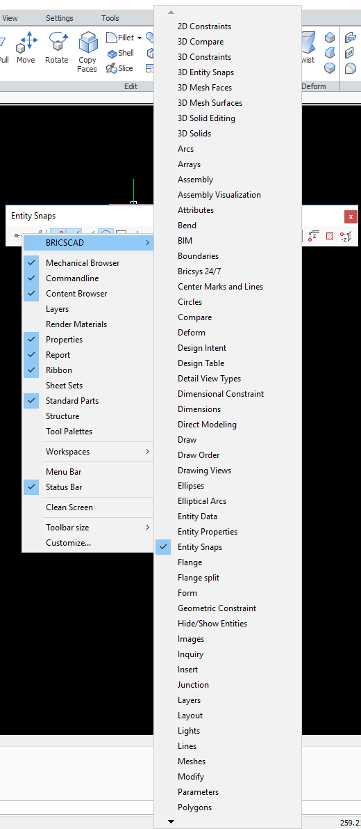
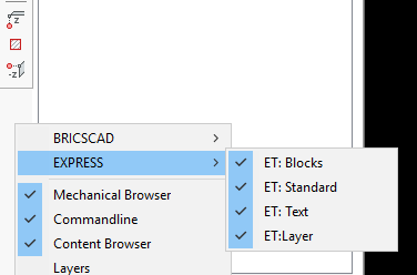
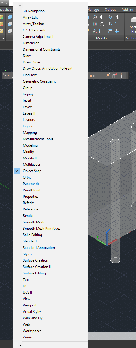
If you have at least one toolbar visible already, things are easy. If you right-click on that toolbar, you will get a menu that allows you to turn on any other toolbar in the same customization group (CUI or CUIx file). Here it is in AutoCAD:

Here’s the equivalent in BricsCAD:

Note that in BricsCAD, the list of toolbars is one level down because the first-level right-click menu in BricsCAD gives you many more interface options.

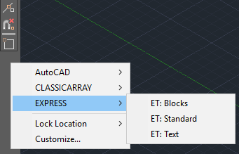
What if the toolbar you want to turn on is in a different customization group? You can get at those easily enough by right-clicking on any blank (unused) area of a docked toolbar area. AutoCAD:

You can do the same in BricsCAD:

The difference with BricsCAD is that you don’t need to have a docked toolbar with spare space in it to access toolbars in different groups. They’re all available by right-clicking any toolbar button, docked or not.

That’s all easy enough, but what if you don’t have any toolbars visible? You’re stuck in a Catch-22 situation. You need a toolbar to click on to load a toolbar. How do you get that first toolbar loaded?

AutoCAD Interactive Method 1

The first trap to avoid in AutoCAD is using the TOOLBAR command. From Release 13 to AutoCAD 2005, that was useful. With the introduction of CUI files in 2006, the TOOLBAR command became a near-useless cut-down version of the CUI command.

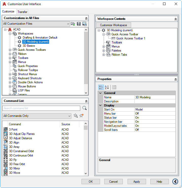
Ignore that. If you’re going to use the CUI interface, use the whole thing. Enter the CUI command. In the top left pane, pick the workspace you want to change:

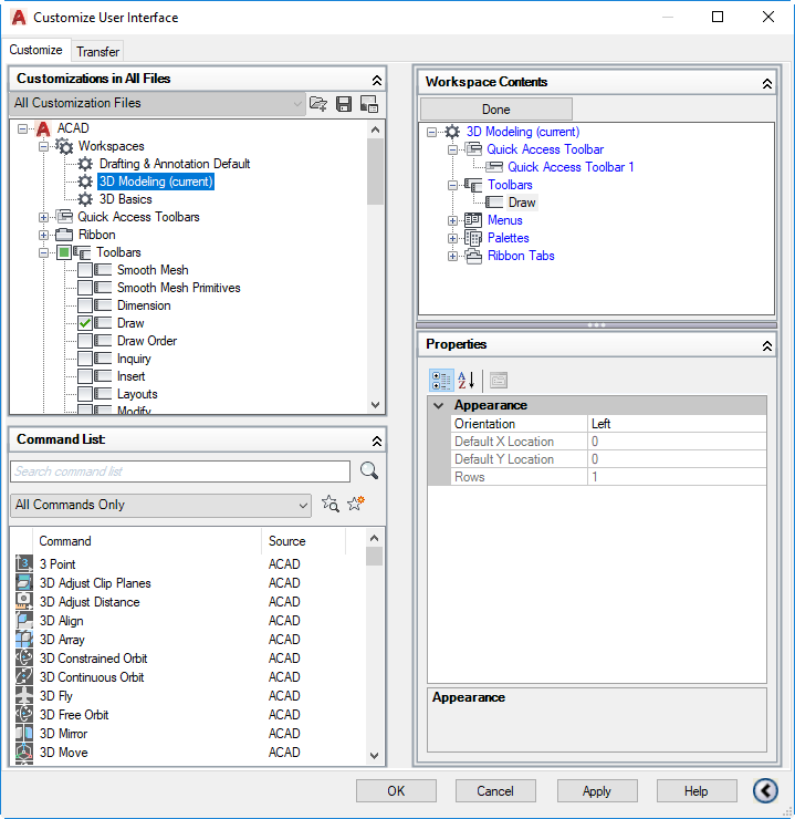
In the top right pane, pick Customize Workspace. In the left pane, expand the Toolbars part of the tree and turn on one of the toolbars:

Pick Done (top right) and OK (bottom). Your chosen toolbar will appear.

AutoCAD Interactive Method 2

If you have your pull-down menu bar turned on, you can get at the toolbars using the Tools menu as shown here:

You can turn on your pull-down menu bar by setting MENUBAR to 1.

Thanks to James Maeding for pointing that out.

BricsCAD Interactive Method

In BricsCAD, you can turn on toolbars interactively even if there are none visible, without having to deal with the CUI interface. Just right-click in any part of the ribbon, and you will see the same menu you get when right-clicking a toolbar area. That gives you access to all of the toolbars in all of the groups.

AutoCAD Command Line Method

If you want to use the command line to turn on a toolbar, you need to use the -TOOLBAR command (note the leading hyphen). You also need to know the name of the customization group and what the toolbar itself. One example is the Object_Snap toolbar within the ACAD group. The command line required is therefore:

-TOOLBAR ACAD.Object_Snap Show

To be sure this will work in all environments, I recommend you add the special characters _ and . thus:

_.-TOOLBAR ACAD.Object_Snap _Show

BricsCAD Command Line Method

In BricsCAD, you don’t need the leading hyphen in the TOOLBAR command (although you can use it if you like). The customization group and toolbar names will be different, but the syntax is the same. For example:

TOOLBAR BRICSCAD.TB_EntitySnaps Show

The recommended special characters also do the same job in BricsCAD:

_.-TOOLBAR BRICSCAD.TB_EntitySnaps _Show

A & B Tip 2 – realistic threads

In this series of posts, I’ll be providing tips that show how to do something in both AutoCAD and BricsCAD, hence A & B.

The Series

The idea behind this series is to provide useful information for several sorts of reader:

  1. AutoCAD users.
  2. BricsCAD users.
  3. People in the process of transitioning from AutoCAD to BricsCAD and who need to know what to do differently (if anything).
  4. People considering transitioning from AutoCAD to BricsCAD and who want to know about the differences and similarities.

Realistic Threads

This post explains how to create realistic-looking threads for screws, nuts and the like in your presentation 3D models. I don’t suggest you do this routinely because it will add pointless complexity to your everyday models, but occasionally you will need to make a model that looks highly realistic. For example, you might need a photorealistic rendering of an assembly or an exploded view for a user manual. This example will use ISO metric parts, but the principles are the same for all threads. I’ll assume you have a basic understanding of creating 3D primitives and the boolean operations (union, subtract and intersect).

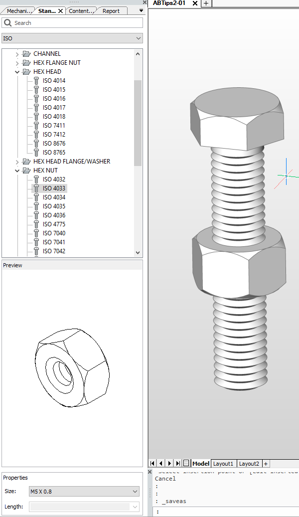
BricsCAD Standard Parts

The first thing to note is that unless you insist on the threads being helical, you probably have very little work to do. Have a look at this ISO M10 screw and bolt. It doesn’t have helical threads, but is it good enough for your needs?

If so, and if you have BricsCAD Platinum, you can save yourself a lot of work. I created this model using the Standard Parts panel on the left. To create the nut, I used ISO > HEX NUT > ISO 4033 > M10 x 1.5. Having chosen my component, I just dragged and dropped it from the panel (the bit that’s highlighted above) into the drawing and specified an insertion point. The screw was similarly easy: ISO > HEX NUT > ISO 4018 > M10 x 1.5 and Length 50.

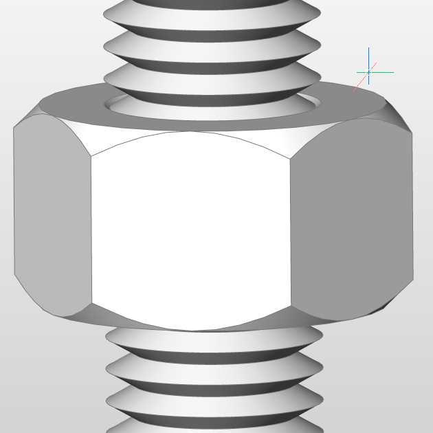
Here’s a close-up. This is good enough for most cases, but if you’re picky you can tell the threads aren’t helical. If you’re really, really picky you can tell that the threads aren’t the exactly correct profile (e.g. no flats on the peaks or troughs).

Also, getting really, really, really picky, there is neither a runout of the thread at the top nor a spherical end at the bottom. If that’s not good enough and you need to construct a model that provides a completely accurate representation, how can you do this? Read on.

Creating helical threads in BricsCAD and AutoCAD

I’m going to recreate the above screw as our example, but will make it dimensionally accurate. For simplicity, I’ll ignore the hex head and just do the shaft part. I’ll use BricsCAD to work through this, but it doesn’t matter. The steps are exactly the same in AutoCAD. There are a few things in BricsCAD’s 3D repertoire that might make things a little easier than in AutoCAD, but I won’t be using them here. I will be switching back and forth between visual styles in order to better show what’s going on with the geometry, so don’t expect consistency between the images.

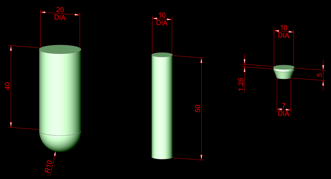
First, construct a few basic parts from solid primitives. Here are the dimensions you’ll need for doing that:

From left to right, we have:

  1. DIA 20 x 40 cylinder that has been unioned with an DIA 20 sphere
  2. DIA 10 x 50 cylinder
  3. DIA 10 x 1.25 cylinder that has been unioned with a truncated cone DIA 10 to 7 x 3.75

The next step is to create the thread. There are two parts to this: the path and the profile. The path is easy: we just use the HELIX command. Specify the center of the middle cylinder as the base, a base and top radius of 5 (but specify the base radius using a known point such as a quadrant), a turn height of 1.5 (that’s the thread pitch) and a height of 50.

You might be tempted to make a simplified profile using an equilateral triangle with a side length of 1.5 (the pitch). Hot tip: don’t do this. Unfortunately, this will cause problems. Both AutoCAD (usually) and BricsCAD (sometimes) may refuse to create the thread because it thinks it self-intersects. You can use a simple triangle profile, but you’ll need to make it slightly smaller than the pitch: scaling by a factor of 0.95 should do.

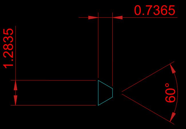
Instead, let’s do it more accurately. The profile can be created as a polyline using conventional 2D techniques. Here are the profile dimensions for an M10 x 1.5 thread:

Note: to be completely accurate, the thread profile should also have a root radius. Feel free to add one if you like.

Either draw this profile in place using an appropriate UCS such that it is vertical up against the middle cylinder, or draw it in WCS and then move it into place using the ALIGN command. Although having the profile located in the right plane and location is theoretically not necessary, in practice it makes creating the thread much less fraught.

Here’s a tip that will save you a lot of trouble later: move the profile very slightly away from the center of the cylinder. A distance of, say, 0.01 will do. Here’s what it should look like if you zoom in far enough:

If you don’t do this, your CAD application will get into trouble later when you try to subtract the thread, because the outside of the thread and the cylinder will coincide, causing problems for the software. Having the outside of the thread just slightly beyond the edge of the cylinder will prevent this issue. Instead of kludging things by moving the profile slightly as described here, you could alternatively draw the profile such that it’s dimensionally accurate but with an outside edge slightly beyond the cylinder. Just make sure you don’t extend the profile so far that you run into the self-intersecting problem.

Next, use the SWEEP command, select the profile and the path. That should give you this:

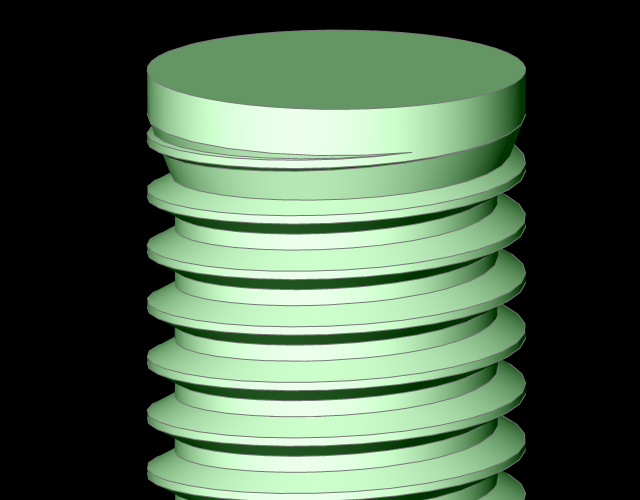
Subtract the thread from the cylinder. Now move the cylinder/cone primitive into place on top of the shaft using CENter osnap and union the two solids, producing the elegant thread runout you see here:

Move the cylinder/sphere primitive into place on top of the shaft using CENter osnap:

Finally, intersect the two solids, producing this domed end to the threaded shaft:

Here’s the finished product in BricsCAD after I added a hex head to the top, unioned the solids together and added a brushed metal material.

Summary

The steps are the same in AutoCAD and BricsCAD:

  1. Create the primitive objects you’ll use later to define the threaded object
  2. Create a thread path using HELIX
  3. Create a thread profile polyline and move it into position
  4. Ensure the profile extends slightly beyond the edge of the shaft
  5. Use SWEEP to create the thread
  6. Subtract the thread from the shaft
  7. Move the cone/cylinder primitive into place and union the parts
  8. Move the sphere/cylinder primitive into place and intersect the parts

If you want to do this in a nut or hole, use the same principles. You just need to reverse the thread profile such that it’s pointing outwards into the hole before sweeping and subtracting.
BricsCAD Shape for Mac

BricsCAD Shape, the free DWG-based 3D direct modeling application from Bricsys, has now been released for macOS (formerly OS X). See my previous post on Shape for details of what it’s all about.

This is the same, just on a different OS. That’s because unlike Autodesk’s versions of its DWG products, the Bricsys versions are not cynically watered down for Apple users. Those users can now do full 3D conceptual modeling as part of a workflow that leads to full BIM (or simply view and edit DWG files if you’re not that ambitious), and without paying for the privilege.

It’s a proper free perpetual licence without usage restrictions, not a demo. You can’t get a perpetual license of DWG-editing software from Autodesk for any money, so by any measure Shape is a bargain.

The Bricsys blog post can be found here. The download page is here.

A Linux version of Shape is expected later.

Video – 3Dconnexion fine tuning in BricsCAD and BricsCAD Shape

The second video in the cad nauseam YouTube channel is more typical than the first in that it’s a tips and tricks video. In this case it only applies to BricsCAD and Shape users, but future videos will provide information for AutoCAD and other DWG-based CAD applications.

Bricsys shows Autodesk how to do mid-term updates – again!

BricsCAD V18.2 for Windows is out. The new stuff in this mid-term update is again showing up Autodesk’s lack of progress with its once-flagship product, AutoCAD. I’m sure Autodesk would love customers to accept that there’s only so much anyone can do with a DWG-based CAD product once it reaches a certain level of maturity. Customers should get used to nothing of significance being added year after year. Diminishing returns, and all that. Pay to continue using the product, but don’t expect it to get better.

What a shame for Autodesk, then, that Bricsys exists. By consistently providing a raft of significant improvements with each full and mid-term release, Bricsys shows up that idea as nonsense. It’s perfectly possible to keep improving CAD at a very rapid rate, particularly if you’re not worried about competing with other products in your range. There’s a reason AutoCAD’s parametrics are restricted to 2D, and BricsCAD’s 3D parametrics in a DWG product proves that the reason isn’t technical. It’s strategic. Also strategic is cutting the guts out of an already much-weakened AutoCAD team, because you would really prefer your customers to be using your trendier and/or more expensive products.

I should point out that BricsCAD V18 customers who have a perpetual license, even without maintenance, will be receiving V18.2 with all its improvements free of charge. Contrast that with Autodesk, which is, despicably, withholding even bug fixes from selected customers. Autodesk’s attitude to customers who aren’t constantly paying up front is one of utter contempt. Autodesk feels entitled to your money; Bricsys wants to earn it.

So what’s Bricsys done to earn your money with BricsCAD V18.2?

Mostly, it’s lots of relatively small-sounding things that add up to significant productivity enhancements. There are several items that are playing catch-up to AutoCAD, such as long-overdue in-place text editing. There are big performance improvements in drawings with PDF underlays due to a smart multi-resolution cache mechanism. The 3D-to-2D generation mechanism has also been significantly sped up. Constraints (2D and 3D, unlike AutoCAD) are easier to create. Several 3D direct modeling operations have been made easier. That also helps with sheet metal design, which has seen other improvements.

In Bricsys BIM V18.2, a lot of smarts have been added. The mechanism for converting CAD models (including those made in BricsCAD Shape) to BIM models, BIMIFY, already did some fascinatingly clever things, but that’s been improved further particularly in the areas of structural member and room recognition. For those of us in Australia, support for our steel sections is very welcome.

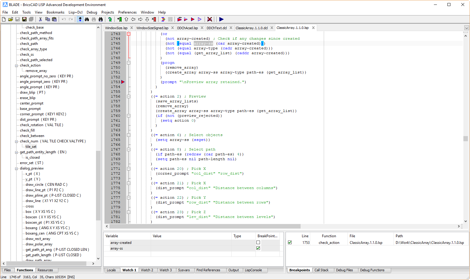
For me, that’s not the big news. Oh, no. The big news for me is a thing called BLADE – the BricsCAD LISP Advanced Development Environment.

If you’re a CAD Manager or in-house developer and you’ve been waiting until BricsCAD had VLIDE, wait no longer. But this isn’t just catch-up. This is a big leapfrog over Autodesk’s sadly neglected IDE for CAD’s primary user programming language. There’s so much good stuff in BLADE that I can’t hope to do it justice here, so I will be covering it extensively in future posts. For now, here’s a statement for you:

If you program in AutoLISP or Visual LISP, you should be doing it in BLADE.

It’s that good. Really. Watch this space for details.

The download is small, the install is fast, it won’t harm your AutoCAD installation, and you can evaluate it free for 30 days. Links:

That awkward moment when I just failed to create BIM

I recently updated my resume, and I thought it might be relevant to include an episode from my early career. This post is an expansion on what I had to say about that episode.

I was managing a tiny CAD training and development company, Educad. Much of my time there was spent developing software called NIDIS (originally called NEEDS), a project that was started in 1987 or 1988 with Nixdorf Computer as the client. It was intended to take over the market among first the home building companies of Western Australia, then Australia, then the World!

What’s special about NIDIS is that it was a precursor to BIM. Using a 3D-adapted version of the 2D Educad architectural software within AutoCAD, designs of domestic homes could be efficiently created and infused with a degree of intelligence. This was then linked to the Nixdorf minicomputer-based software that contained pricing and other information about the various building components. This combined system enabled accurate quantity take-offs to be performed.

This was supposed to be a short project, but due to a massive amount of “scope creep” it took two years. I was really pushing the limits of what AutoCAD could be persuaded to do at that time and had to break new ground in several areas. Some of it was a kludge, but I made it work. Finally, the software was essentially completed, with a custom tablet menu (remember those?), full documentation and everything. Nixdorf CAD-spec PCs with big screens, tablets, AutoCAD and NIDIS were installed in the drawing office. It was successfully tested in Beta. The take-offs were very accurate. Everything looked good to go.

Then, two weeks before it was due to go into production, this project died. The building company that was sponsoring it, Mansard Homes, went into liquidation as it struggled unsuccessfully with the combined effects of very high interest rates and bad publicity about poor building quality and cost overruns. Nixdorf dropped the whole project like a hot potato and the product was never sold. I didn’t have any rights to the software and couldn’t do anything with it.

But it was software that was based around a 3D model of a building that contained some intelligent information, albeit extremely crude by today’s standards. I wrote, quite literally, Building Information Modeling software. It was completed in 1989, before the name BIM had even been used. The idea had existed since the mid 70s, but I didn’t know that at the time so I made it up as I went along.

I didn’t actually invent BIM, but I made something that resembled BIM that actually worked. And then it didn’t.

This is easily the most spectacular failure of my career. Still, I’m kind of proud of it.

Edit: for historical context, this video shows an unrelated system that was developed at about the same time as NIDIS.

Why Bricsys makes the best AutoCAD for Mac

Bricsys has just released BricsCAD V18 for Mac. Here’s the download link and here are the release notes.
BricsCAD V18 is an excellent DWG 2018-based CAD application, and the Mac version lacks little in comparison to the Windows version. It’s so much more capable than the perpetually half-baked AutoCAD for Mac that I struggle to comprehend why anybody with the choice would even contemplate the notably inferior and seriously overpriced Autodesk offering.

That’s not just opinion, it can be supported objectively.

Price first. US prices are shown here for a single standalone license over five years, inclusive of the cost of upgrades. The BricsCAD prices therefore include maintenance (it’s optional); the Autodesk prices are for subscription (not optional). No temporary discounts have been included. I have excluded bargain-basement BricsCAD Classic because it lacks the full set of programming and 3D modeling tools. I have assumed that there will be no price increases over the next five years. Given recent history, that’s probably close to the truth for Bricsys prices. Autodesk, not so much.
Year BricsCAD Pro BricsCAD Platinum AutoCAD
1 970 1330 1470
2 240 240 1470
3 240 240 1470
4 240 240 1470
5 240 240 1470
Total 1930 2290 7350

It’s worth noting that if you want to stop paying Bricsys, you’re left with the latest version to use indefinitely. You can change your mind and get back on the upgrade train later, if you like. That sort of flexibility is long gone at Autodesk, where subscription means no pay, no play. If you stop paying, despite having paid 3.2 times as much for your software over the five year period, you’re left with nothing.

Now, features. You may have noticed that Autodesk is now too embarrassed to list the differences between the Windows and Mac versions of AutoCAD on its web site. The Compare AutoCAD vs. AutoCAD for Mac page is now a shadow of its former useful self, devoid of all detail. If you want to get a reasonable idea of what’s going on with AutoCAD for Mac’s deficiencies, you can check out my post about the 2017 release that lists the missing features.

Alternatively, you can have a look at the equivalent Bricsys comparison page, which you should probably do anyway before spending any money. It’s strange that you now need to visit a competitor’s page to get detailed information about an Autodesk product, but in the CAD world these are strange days indeed.

It’s important to note that the Bricsys comparison page has issues; while the BricsCAD columns are up to date, the AutoCAD columns are a year behind. That page definitely needs an update in order to provide a fair comparison. Don’t rely on it completely (e.g. all of the listed products except BricsCAD V17 for Linux use DWG 2018 as the native format, not DWG 2013), but it will give you an approximate idea. Look at the little red X marks in the rightmost column and you’ll see that a whole bunch of the missing AutoCAD for Mac features, even after all these years, are very significant and their absence could rule out the product for you. Don’t expect much in the way of future improvement. either. AutoCAD for Mac is in maintenance mode, just like the full product.

BricsCAD for Mac is not just more fully-featured, it’s ironically also more AutoCAD-compatible than Autodesk’s effort. For example, try to run a selection of LISP routines in both products. Almost all of it will run just fine in BricsCAD. Anything that uses ActiveX or DCL (dialog box) calls simply won’t work in AutoCAD. You might be all right with some simple routines (if it was written for AutoCAD for DOS then it will probably be fine) but any LISP even moderately sophisticated is going to fail.

BricsCAD for Mac doesn’t just provide capabilities that AutoCAD for Mac doesn’t have and never will, it offers something more than that. It offers a path beyond basic drafting. You can abandon all hope of Revit for Mac – that won’t be happening. AutoCAD-based vertical products? Nope. Inventor OS X? Forget it. But the availability of a product like Bricsys BIM for Mac (not priced above – it’s US$770 extra if purchased seperately) is an obvious drawcard for Mac-happy architects. You can create 3D parametric models on your Mac if you use BricsCAD Platinum, and you can create them without straying far from a familiar AutoCAD-like environment. Sheet metal? Sure (at extra cost).

If you’re a Mac-only person and you’re wedded to Autodesk, you’re not only being ripped off, you’re following a dead-end path. Time to check out the alternatives.

BricsCAD Shape – can a free DWG product be a BIM game-changer?

At the Bricsys 2017 Conference in Paris, one of the biggest surprises was the announcement of BricsCAD Shape. This product was demonstrated live, very impressively, in pre-release form. As I live-tweeted at the time, the demo jock was able to create a pretty decent architectural model in minutes, from scratch, very easily. That product has now been released.

What is BricsCAD Shape?

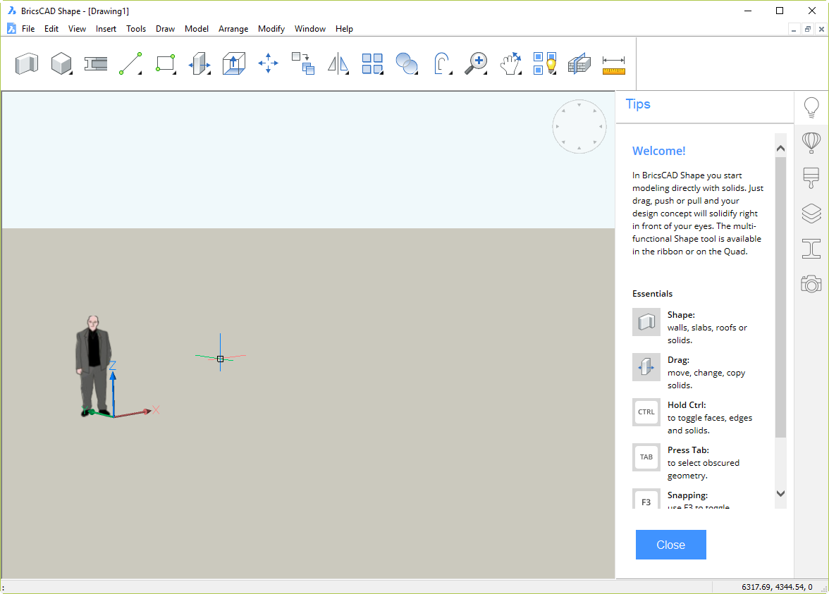
Shape is a 3D direct modeling application. At the core, it’s a simplified BricsCAD BIM. That means it’s small, fast, stable and it uses 2018 DWG as its native format. These are all good things. It’s obviously aimed at the AEC market, but there’s nothing to stop anyone using it for anything. Use it as a lightweight DWG viewer/editor if you like.

As you can see, it has a very simple, clean, cut-down interface. That dude is French Architect Jean Nouvel, by the way. He’s a block; you can erase him. He doesn’t appear in DWG files from other sources you open in Shape.

The idea is to do most of your work with the 18 buttons in this mini-ribbon/monster toolbar thing:

For less common operations, there is a set of pull-down menus. Although it’s hidden by default, you can even turn on a command line (Shift+F2) that will be very familiar to AutoCAD and BricsCAD users. Try to do without it; you will then discover how the excellent Quad Cursor interface (inherited from BricsCAD) uses AI technology to save you time and clicks.

How do I get it?

Click this link, enter your email address (no, they won’t sell it to spammers), and download away. Unlike Autodesk downloads, there are no nasty Akamai download managers to contend with, no multi-stage install processes, no massively bloated files, just a straightforward download of a 212 MB MSI installer. Time to download for me on ADSL2 was 2m 56s. The install time, including user interactions was 36s. Time for the first startup, including online registration, was 15s. That got me to the startup screen. The time for the first drawing startup was another 10s.

You can be using Shape in under 4 minutes. That is, you could be using it yourself in less time than it takes to read what I have to say about it.

How is it licensed? How much is it?

It’s a perpetual license, and it’s free. Bricsys has stated that it will always be free. Not much to complain about there.

So what’s in it for Bricsys?

The problem Bricsys faces in churning over large numbers of Autodesk’s disgruntled customer base is not the products. The products are fine. BricsCAD is notably superior to AutoCAD in a bunch of significant ways (while remaining inferior in a handful of less important ways), and costs a fraction as much.

No, the problem Bricsys faces is in persuading large numbers of people to try its products. Shape is an attempt to make that happen. It’s an ice-breaker in a way that goes beyond the usual 30-day free trial product.

There’s hardly any bar to entry; anybody with an email address can own it with zero investment. The interface has been kept very simple and there are a whole bunch of bite-size tutorial videos that demonstrate how to do things. If this product can create a buzz and get people to use a Bricsys product, half the battle is won. The models it creates are ready to be easily taken to the next stage using the full, paid product, BricsCAD BIM.

It’s not SketchUp
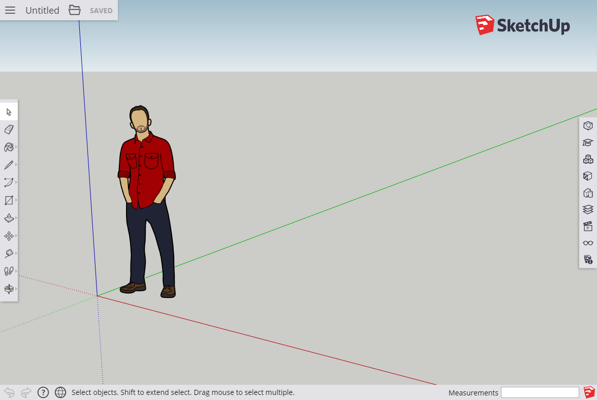
There are superficial similarities between Shape and the discarded-by-Google product, Trimble SketchUp.

However, there are very significant differences. SketchUp Free is a cloud-based product that works inside your browser (the paid product is currently a desktop product). Shape is a standalone application that does not require the Internet. SketchUp has its own file formats; getting those models into CAD or BIM is fraught. Shape is not just using industry-standard DWG file format, it’s a proper, efficient, accurate CAD application. Because it’s a cut-down version of what Bricsys is hoping you will use to fully develop the models later, there is no translation. The model you build in Shape opens directly in BricsCAD BIM where automatic classification of building elements can take place.

BricsCAD Shape. It’s free, it’s easy, it’s DWG, it’s CAD, it’s 3D, and it’s a pathway to BIM. It could change the game. I have no way of predicting whether that will happen. But if it does, it’ll be another kick in the guts for a dormant Autodesk that has largely given up on improving its products.

AutoCAD 2018 for Mac – welcome to twenty years ago

In the past, I’ve described how AutoCAD for Mac was released half-baked (as I predicted) and has remained half-baked ever since.

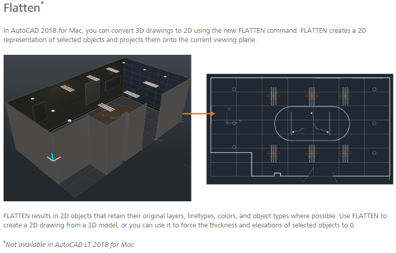
But wait! Autodesk has proudly announced AutoCAD 2018 for Mac. Skimming through that blog post, I must admit my jaw dropped when I saw some of the new features. This one, for example:

This “new feature” was first provided to AutoCAD users in the 20th century. It was an Express Tool in AutoCAD 2000 (released 1999) and was absorbed into mainstream AutoCAD a few years later. The alias editor goes back even further, to the Release 14 Bonus Tools (1997). That one was absorbed into AutoCAD in 1999. Some of the other new features are also old. Migrating your settings was new back in the century that started without powered flight. Now, not so much.

These features are new to AutoCAD for Mac, of course, and that’s kind of the point. Autodesk is advertising, as new, features that were born before some of the adults who are now using their products.

There are other very important features (e.g. DCL support, essential for LISP compatibility) that date back even longer (Release 12, 1992) and which are still missing from AutoCAD for Mac. That’s right, in some areas AutoCAD for Mac is a quarter of a century behind. And counting.

On the bright side, you do now get access to the pointlessly-changed 2018 DWG format. A couple of features are reasonably new additions, but they represent a small subset of the small number of minor improvements in AutoCAD 2017 and 2018 for Windows. If anything, the rate of improvement of AutoCAD for Mac is lagging behind even the glacial progress of AutoCAD for Windows, despite starting from a much lower base point.

I note with interest that Autodesk’s comparison page is now hiding the detail of the differences between the full product and AutoCAD for Mac. I guess if you have two identically-priced products and one’s missing a bunch of stuff, you might be tempted to hide the fact from your potential customers. This post of mine from last year will give you some idea of what Autodesk’s not telling you about what’s missing from AutoCAD for Mac. Clue: it’s a lot.

Mac users pay full price for their product and deserve much better than this. If you want information on a full-featured “AutoCAD for Mac”, don’t bother looking for it from Autodesk. Try Bricsys instead.

Draping images over surfaces in Civil 3D

Having recently overcome various difficulties to successfully drape an image over a surface in Civil 3D, it may be useful to pass on a few points I have learned. There are various posts and videos out there that helpfully go through this process, but some of them (including Autodesk sources) contain information that is irrelevant or just plain wrong, and none of them contained all  of the information I needed to complete the task.

I used Civil 3D 2015 for this, but the principles apply to all recent releases. Here is the basic sequence required:

  1. In the drawing containing the surface, attach the image to your drawing using your preferred method (ImageAttach, Xref, ClassicImage). I’ll assume you’re familiar with what you need to do to get the image correctly scaled and aligned with the surface.
  2. Invoke the DrapeImage command, which will show you this dialog:DrapeImage01
    Make sure this is set for the image you want to drape and the surface you want it draped over. You can change the Render Material Name to whatever you like, or leave it as the default. Pick OK.
  3. You no longer need the image attached to the drawing and it will probably only confuse matters, so you can use use the Xref or ClassicImage command to detach it.

If you’re really lucky, that’s it. You will have a lovely-looking surface with a draped image over it. However, at this stage that’s pretty unlikely. Don’t panic! You also need to ensure the following conditions are in place:

  1. The surface will need to use a surface style that includes triangulated surfaces so the image has something to drape over. In the Toolspace, under Surfaces, right-click on the surface and pick Surface Properties…, then change Surface Style to anything with triangles, triangulation or TIN in the name (this varies depending on the template used). If you don’t have such a style available, you’ll need to make your own or edit an existing one using the button with a pencil in it.DrapeImage02
  2. While you’re in the Surface Properties dialog, have a look at Render Material. That should be showing the Render Material Name you specified in step 2 above. If it isn’t, make sure it is. Pick OK.
    Bonus tip: if you later need to remove the draped image from the surface, you can do so by changing the Render Material to something else (e.g. ByLayer).
  3. Still seeing nothing useful? Make sure you are using the Realistic visual style. You can get at the Visual Styles Manager using the VisualStyles command, but in recent releases it has been made easier to switch visual styles using the in-canvas control:DrapeImage03
  4. Still nothing? Try turning off Hardware Acceleration. Right-click on that glowing blue blob thing in the lower right corner and pick Graphics Performance…DrapeImage04That will give you a dialog with a Hardware Acceleration switch. Turn it off, pick OK and (hopefully) voila!

Note that the above conditions need to be in place when plotting, too. You might not expect hardware acceleration to make a difference to plotting, but in this case, it does.

Let’s critique AutoCAD’s parametric constraints

One of the big-ticket features of AutoCAD 2010 was parametric constraints. This was old hat for many applications, even some based on AutoCAD like Mechanical Desktop. Parametrics and constraints already existed in vanilla AutoCAD in the guise of dynamic blocks, but this was the first time ordinary AutoCAD allowed ordinary AutoCAD objects to be constrained and linked to parametric dimensions.

Contraints mean that you can draw some objects and tell them that they are only allowed to behave in certain ways. For example, two lines have to remain parallel to each other. Parametrics mean that objects can be tied to special dimensions such that the dimensions drive the objects, not the other way round.

How good a job has Autodesk done with creating and improving this feature in AutoCAD? Has Autodesk done its usual trick of releasing a half-baked feature and then ignoring it to death? In one vital respect, the answer is a resounding yes. AutoCAD’s parametric constraints can only be applied to 2D objects. Draw a shape using a polyline, apply constraints and parameters, and adjust them to make things work properly and appear correctly. Now extrude the polyline to convert it to a 3D solid. Your carefully applied constraints and dimensions are instantly exterminated. This was a huge and obvious hole in the feature when it was introduced, but on the fourth iteration of this feature in AutoCAD 2013, that gaping hole remains resolutely unfilled. I guess Autodesk is keeping AutoCAD’s parametrics in this flattened state in order to protect Inventor from internal competition.

This 3D failing is very obvious, but I’m interested in more subtle aspects than that. As my experience with parametrics in other applications is limited, I’d like to encourage you to provide us all with the benefit of your knowledge. How does the AutoCAD 2013 implementation compare with that found in Inventor? Solidworks? Mechanical Desktop? How easy and efficient is it to use, in terms of creating usable parametric drawings and manipulating them? Is it logical and reliable? Are there any missing capabilities? The Devil is in the details, so has Autodesk overlooked any?

I’d also encourage less experienced users to comment. If you don’t want to enter a new field with your own drawing started from scratch, have a look at this sample drawing courtesy of Autodesk’s Dieter Schlaepfer. Here’s what Dieter has to say about it:

For your amusement, here’s a backyard deck that I whipped up a while back as a parametric design. It’s saved in R2010 format. After you turn on the geometric and dimensional constraints, open the Parameters Manager and try changing the value of Angle from 90 to 120, 130, and 140 degrees. Also, try changing the value of Tread from 18 (inches, sorry) to 16 or 20.

No question that this takes a bit of experience and it’s not for everyone.

If you prefer to embark on your own journey of discovery, here are some deliberately vague instructions. As always in AutoCAD, there are many ways of doing the same thing, but this will do to get you started:

  1. Draw a closed polyline describing an open L shape (let’s say it’s a metal plate). Make sure the corners are square, but you don’t have to make the sizes totally accurate.
  2. Use the AutoConstrain feature on the polyline.
  3. Perform a few grip edits on the constrained polyline so you can see what difference the constraints have made.
  4. Use Dimensional Constraints Aligned to dimension the plate in four key places: each overall plate width dimension and each of the leg width dimensions. Hint: press an initial Enter to use Object mode before selecting the object. When you are prompted for the dimension text, either press Enter if it’s was drawn accurately or enter the correct size if it wasn’t. The plate should change to the size you enter.
  5. If you want these dimensions to show up on plots, you will need to make sure their Constraint Form is set to Annotational. You can use the Properties palette to do this. You may also need to use DIMEDIT Home to put the dimension text in the usual place.
  6. Try using a few normal editing operations on the objects (e.g. STRETCH, COPY, ROTATE, TRIM, grip edit) to see how they react.
  7. Try modifying the objects by double-clicking on the dimensions and changing the values, then using Parameters Manager.

So, how was that? Easy? Difficult? Useful but awkward? Any areas where efficiency could be improved (e.g. too many clicks required for common operations)? Can you use this in your work or is there some problem lurking that appears to be a dealkiller?

Edit: Here’s a more complex example from Dieter: https://www.dropbox.com/s/n5hng961nj1dkzy/gasket1.dwg?m

3DConnexion device support in AutoCAD

Do you have a 3DConnexion device (3D ‘mouse’) and use it in AutoCAD or AutoCAD-based products? What do you think of the way it works in the most recent releases of AutoCAD?

From AutoCAD 2011 on, Autodesk provided built-in support for these devices. Has that made things better or worse than in earlier releases? If you’re having problems, exactly what are they and how does it affect your ability to work with AutoCAD in 3D? Is the 2012 support any better than 2011? How does AutoCAD’s support for these devices compare with that of other products?

Siemens 0, Autodesk (April) 1

Personally, I find most April fool jokes to be pretty lame. I considered doing one myself, and had what I thought was a pretty convincing idea, but finally decided against it. Maybe next year.

This year, there was one definite exception to the lameness rule. It was well set up, clever and funny. Siemens killed it. Or, to be more accurate, they foolishly attempted to kill it. Fortunately, the Twitter CADville app is still alive and even now being tended by somebody with a fine sense of humour, as you can see from tweets like this:

Sometimes you will see duplicate messages. That can happen after downtime. You want better, write your own CADville #cadville.

Sometimes, the cloud is a big server farm. Othertimes, is a crappy laptop that needs to go to the programmer’s girlfriends house. Back in 1h

Once Siemens pulled Mark Burhop’s corporate blog post, in an attempt to protect Mark, Deelip removed his own related post (edit: now restored). But the very idea that you can hide stuff like this once it has been blogged about is plainly ludicrous. Returning wine to a shattered bottle would be much easier.

Ralph describes the CADville story here, you can also see it on Twitpic here, and the original FAQ has been reposted here. Now I’m posting about it on a blog that gets about 90,000 page reads a month. I expect there will be a fair bit of comment buzzing around the CAD community for a while, none of which will reflect well on Siemens.

If this gag had been left to run, I would have either not heard about it at all, or would have noticed it as a funny little episode that showed how cool it was that Siemens doesn’t fit the ‘humourless German’ stereotype. The failure of this futile censorship attempt is a classic case of the Streisand Effect. Apparently, there are people with corporate clout at Siemens who either haven’t heard of it, or delude themselves into thinking that social media are somehow controllable from on high. Nope, sorry, think again.

Deelip said this on Ralph’s blog, and it sums it up nicely:

Yes, this whole thing could and should have ended differently. What I find odd is that CAD vendors talk about social networking and social media and how they are embracing it in different forms. What Mark tried to do was exactly that. He got some of us to blog, others to tweet, irrespective of our affiliations, so that this prank (which is exactly what it is) would look as real as possible. I did my part.

Too bad Siemens does not get what social networking and social media is actually all about.

Congratulations, corporate klutzes, you have succeeded in making your company look completely clueless. Out of touch much? Duh!

Compare this with Autodesk. OK, Scott Sheppard’s Autodesk Love Maker 2011 joke didn’t have me ROFLMAOing or even LOLing, and it was pretty obviously an April fool, but it was still pretty well done. The fact that Autodesk corporate doesn’t throw a hissy fit over stuff like this indicates that it’s at least partly human. The fact that Scott can put a funny picture of his CEO (Pointy Haired Bass) on his blog and still remain employed tells me only good things about Autodesk corporate.

The contrast with Siemens is as stark as it could be.

Edit: Mark (not Matt – apologies) has now restored his post and provided an explanation (of sorts) about the post being pulled. I have asked for a clarification.

Carl Bass on TV

Autodesk big cheese Carl Bass gets a friendly interview on NBC’s Press:Here (amusing name, “press colon here”). It’s kind of funny seeing CAD described by non-CAD people (the presenters, not Carl). Among other things, he discusses being fired by Carol Bartz, Autodesk’s role in Avatar, the benefits of piracy, iPhones, 3D printing, open source and Autodesk being green. I’ve embedded the two Bassy bits here for convenience; these embeds will display ads that are not under my control.

Edit: I’ve removed the embedded clips as they were slowing down this whole site for some users and even disabling some features. If you want to view the interview, please go to Press:Here and look at Episode 46 Autodesk Part 1 and Episode 46 Autodesk Part 2.

Open Letter to James Cameron

James, you don’t know me, but I see you have been getting involved in CAD events lately, which is my area of interest. Autodesk University 2009 attendees got a sneak preview of Avatar and you were a key speaker at Solidworks World 2010. I absolutely loved Avatar. It’s the only film I’ve ever seen where I immediately wanted to watch it again. Yes, it’s possible to poke holes in the plot, but that applies to 99% of films and anyway, this film isn’t about the plot, is it? It’s about the breathtaking visuals. I was dreaming about Pandora for days afterwards; good job.

I grew up in the 70s with the music of Yes and the artwork of Roger Dean. That the visuals of Pandora are based on Roger’s artwork is undeniable, and the film benefits immeasurably from the floating mountains, spectacular arches, dragons and even skin patterns that are so obviously lifted from Roger’s work. Why then, when I stayed to watch the credits at the end of the film, did I not see Roger Dean credited? I understand that Roger has received no monetary credit for his contributions, either.

James, you know the right thing to do. Please do it. Otherwise, instead of thinking of you as the guy behind the most visually impressive film ever, I’ll think of you as the jerk who ripped off Roger Dean. Over to you.