
In this series of posts, I’ll be providing tips that show how to do something in both AutoCAD and BricsCAD, hence A & B.
The Series
The idea behind this series is to provide useful information for several sorts of reader:
- AutoCAD users.
- BricsCAD users.
- People in the process of transitioning from AutoCAD to BricsCAD and who need to know what to do differently (if anything).
- People considering transitioning from AutoCAD to BricsCAD and who want to know about the differences and similarities.
Counterbored holes
This post continues to explain more about how to put holes in your 3D models. In this post I’ll be describing how to construct counterbored holes. Hint: the most efficient method is described last.
I’m going to start with this model and use different methods to create three counterbored diameter 10 holes that go through the block, each with a diameter 20 x 18 deep counterbore. I’ve placed circles of diameter 10 and 20 in place to indicate where the holes are going to go, and in some cases to act as the basis for extrusion.
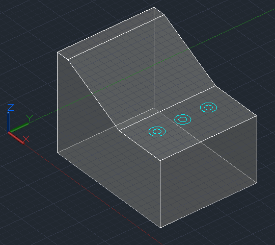
If you’re unsure about how to locate these circles in exactly the right spots in 3D space, see my earlier drilling holes posts, part 1 and part 2.
Extruding circles
Assuming we have appropriate circles to work with, we can extrude them to create cylinders, then subtract them. This works in basically the same in both AutoCAD and BricsCAD, but there are differences:
| AutoCAD | BricsCAD |
Invoke the EXTRUDE command: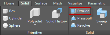 |
Invoke the EXTRUDE command: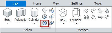 |
Select the inner circle and press Enter to complete the selection process: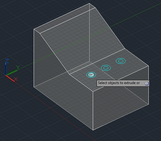 |
Select the inner circle and press Enter to complete the selection process: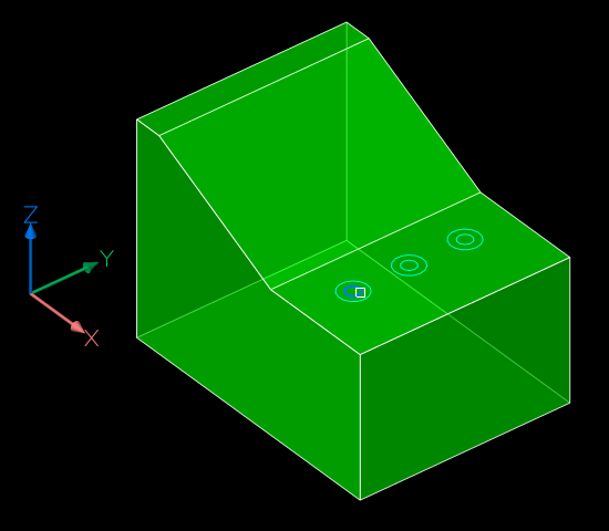 |
Move your cursor down and click when the extrusion goes beyond the bottom of the block: |
Enter a negative number that equals or exceeds 100 (the thickness of the block): If you just pick a point as per AutoCAD, the extrusion will go up rather than down. It’s also possible to point to the direction and amount to extrude by using the Direction subcommand and picking two points, for example a top and bottom corner of the solid. If you just pick a point as per AutoCAD, the extrusion will go up rather than down. It’s also possible to point to the direction and amount to extrude by using the Direction subcommand and picking two points, for example a top and bottom corner of the solid. |
Repeat the above process for the second circle, but this time specify an extrusion height of 18 while the cursor is located such that the extrusion is going down rather than up: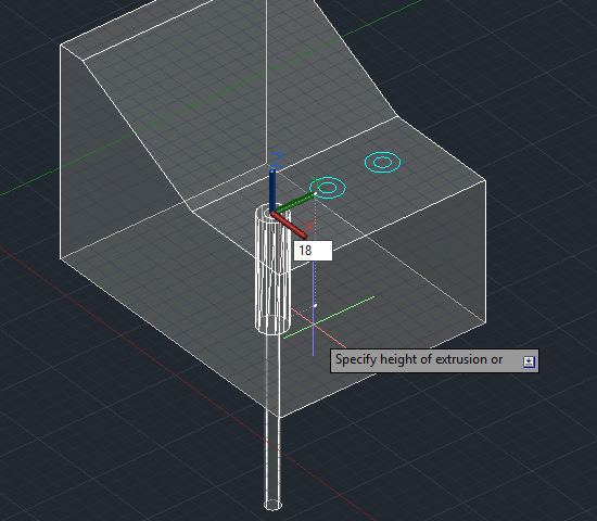 |
Repeat the above process for the second circle, but this time specify an extrusion height of -18. It has to be negative, otherwise the extrusion will go up even if you’re pointing down (unlike AutoCAD).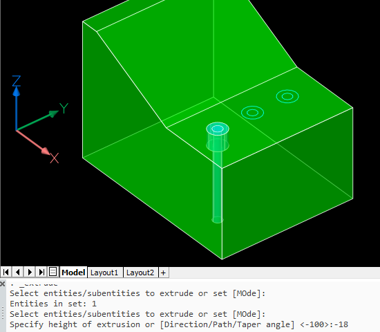 |
We’ll subtract these cylinders later.
Drawing cylinders
You can draw cylinders to subtract without needing construction circles. In this case one of the circles is just used to help locate the cylinder center point, but you can use other methods that involve no construction geometry instead, as explained in my first drilling holes post.
| AutoCAD | BricsCAD |
Invoke the CYLINDER command (Solid, not Surface):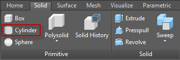 |
Invoke the CYLINDER command (Solids, not Meshes):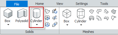 |
Locate the center of the cylinder, in this case using the center object snap: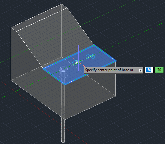 |
Locate the center of the cylinder, in this case using the center entity snap: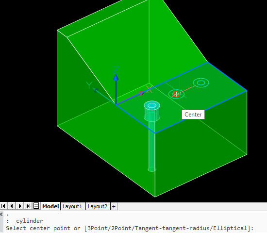 |
Enter a radius of 5: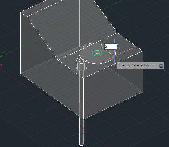 |
Enter a radius of 5: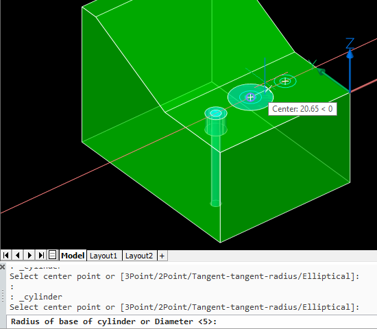 |
Move your cursor down and click when the extrusion goes beyond the bottom of the block: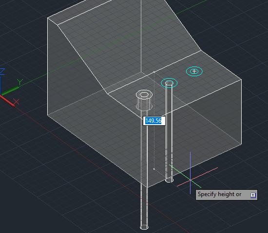 |
Move your cursor down and click when the extrusion goes beyond the bottom of the block: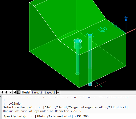 |
Repeat the above process for the second cylinder, but this time specify a height of 18 while the cursor is located such that the extrusion is going down rather than up: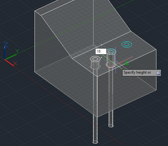 |
Repeat the above process for the second cylinder, but this time specify a height of -18: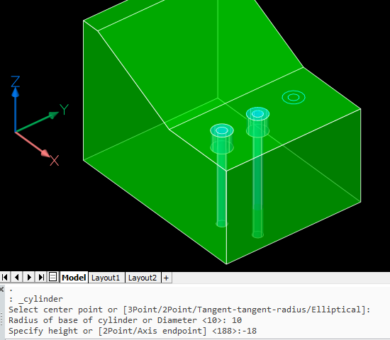 |
Subtracting the cylinders
We can subtract all four cylinders at once to create two of the counterbored holes. This process is the same in both applications.
| AutoCAD | BricsCAD |
Invoke the SUBTRACT command: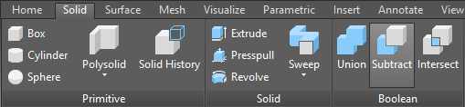 |
Invoke the SUBTRACT command: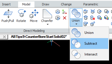 |
Select the main solid as the object to subtract from and press Enter to complete that selection. Then select the cylinders to remove. This is easiest with an implied window. Pick a corner point containing no objects, starting on the left. Then pick the opposite corner to the right.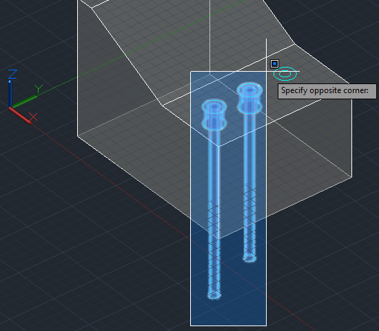 Press Enter to complete that selection and the command. Press Enter to complete that selection and the command. |
Select the main solid as the object to subtract from and press Enter to complete that selection. Then select the cylinders to remove. This is easiest with an implied window. Pick a corner point containing no objects, starting on the left. Then pick the opposite corner to the right.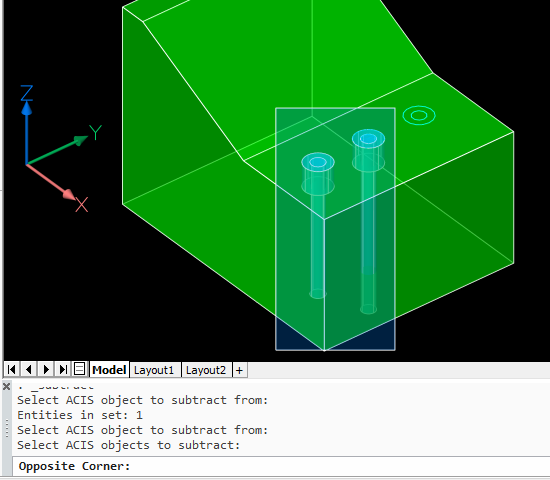 Press Enter to complete that selection and the command. Press Enter to complete that selection and the command. |
End result: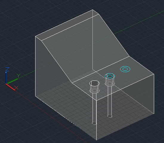 |
End result: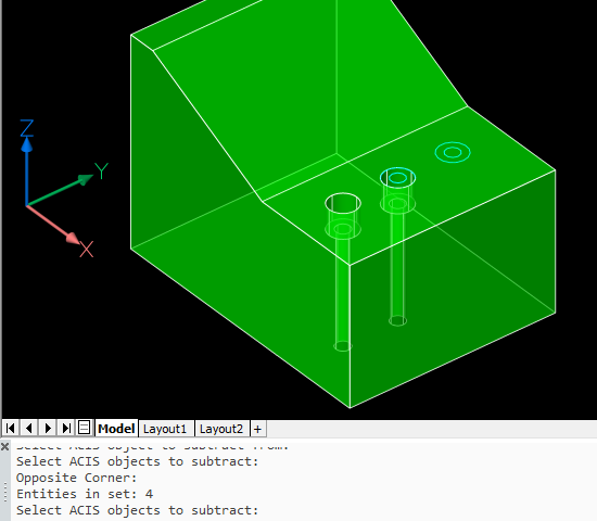 |
Note that the first method replaces the circles with cylinders. The second method only uses the circles to help locate the center; they don’t really need to be there at all and are ignored.
Presspulling or Push/pulling
As described before, planar objects such as circles can be extruded by presspulling them. We’ll use that method to create the third counterbored hole. In this case, the operations differ somewhat between AutoCAD and BricsCAD.
| AutoCAD | BricsCAD |
Hold down Ctrl+Shift+E to turn on dynamic presspull mode, hover over the space between the two circles and pick: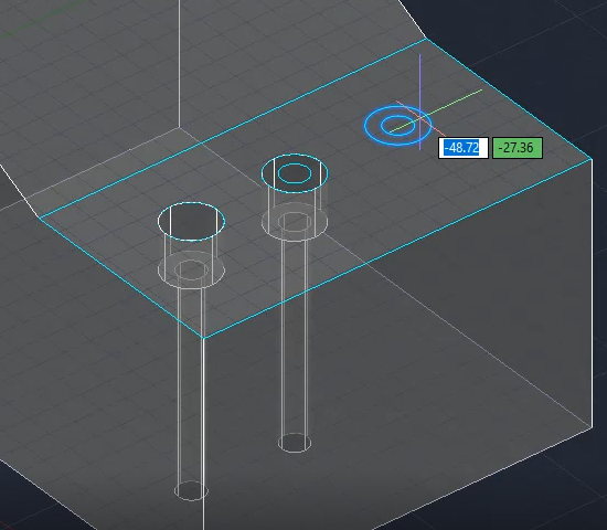 |
Hover over the inner circle. You should see the Quad Cursor appear, suggesting a push/pull operation. Pick the icon to accept that operation: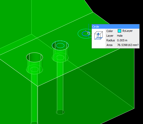 |
Now you can release Ctrl_Shift+E. Move your cursor down and enter 18: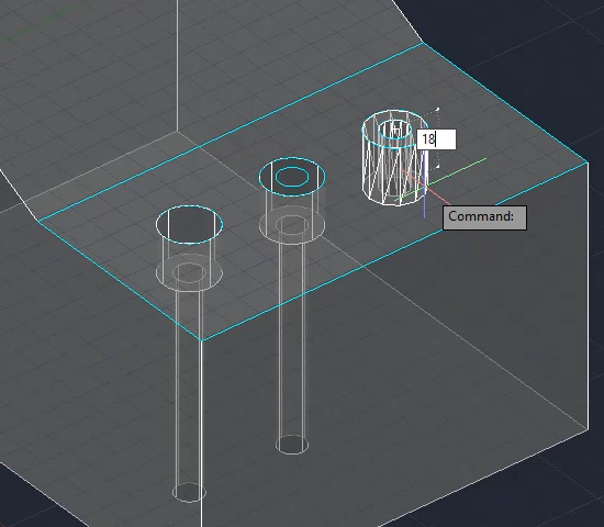 |
Move your cursor down beyond the bottom of the block and pick.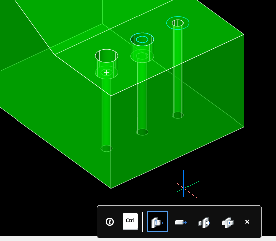 Note the on-screen reminder that you can hit the Ctrl key to switch between several different types of push/pull operations. We can ignore this because in this case we want to use the default. However, it’s worth noting that this feature exists because it’s very handy. |
Hold down Ctrl+Shift+E to turn on dynamic presspull mode, hover over the inside of the inner circle and pick. Release Ctrl+Shift+E, move your cursor down beyond the bottom of the block and pick: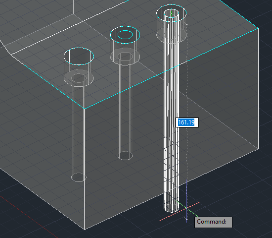 |
Hover over the outer circle and pick the push/pull icon on the Quad Cursor. You could enter a height of -18, but in this case there’s a handy nearby hole counterbored to the correct depth and we can just pick the center of that instead: |
In the AutoCAD presspull end result, the circles are left behind so if you don’t want them you will need to erase them.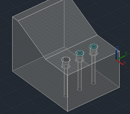 Note also that your UCS origin is changed by this operation even if dynamic UCS is turned off. To restore it, use UCS Previous or use the UCS menu under the ViewCube to change it to World or any other named UCS: Note also that your UCS origin is changed by this operation even if dynamic UCS is turned off. To restore it, use UCS Previous or use the UCS menu under the ViewCube to change it to World or any other named UCS: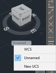 |
In the BricsCAD push/pull end result, the circles are converted to holes so no more action is required. No UCS restoration is necessary.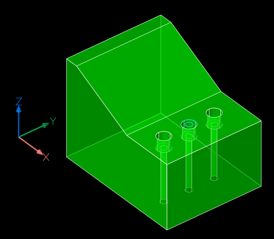 |
Summary
Assuming you have construction circles in place, presspulling is the most efficient of the three methods in AutoCAD, even allowing for the tidy-up required at the end.
BricsCAD’s Quad-based push/pull operation is the most efficient method of the lot. Hover, pick, pick and hover, pick, pick is enough to create a counterbored hole.
Next: countersunk holes.
Steve,
For some reason the right side of the Bricscad column is hiding underneath the sidebar on the right of the page. I estimate about 10% of the column is hidden.
I’m using IE11.
Thanks for the feedback. What screen width do you have?
I’ve dropped the sidebar widths a bit, is that better?
Sorry, I’m late in coming back to look at this again.
Yes, it looks good now.
Or, you can save a pile of steps by inserting the block of a half profile (region, closed pline) at the center of the conterbore/sink base point – explode, revolve, copy as needed and subtract. You can include chamfers, radii, o-ring grooves in a tiny number of block files or a very convenient dynamic block of hole_makers. 3D dynanic blocks would be more betterer. You can also add the profiles of certain tool combinations so that clearances expose/display themselves on a handy tool_cleatance layer. The joys of semi-automation. – Bill
Indeed, you are entirely correct. Using blocks (and 3D parametric components in BricsCAD) is coming to this series eventually.
Sorry. I saw 647 images where three would suffice. My auto productive syndrome kicked in.
Your feedback is welcome, and I’m happy to hear about your techniques because I might not have even thought of them.
You’ve probably worked out that this series is aimed at people with significantly less experience than you. The intent is to provide detailed instructions showing how to do things in different ways, because each of those ways introduces skills that are likely to be useful in other areas.
We’re heading towards efficiency (in this case we eventually got to 2 x hover, pick, pick), but the journey rather than the destination is the most important aspect.
I’ve never done anything in 3D like this.
If I ever had to, I’d probably come back here to get started.
It’s good to learn how to walk before you try to run.
I’d like to see A&B tips for Civil 3D type stuff: import cogo points, create a surface, create an alignment, create a profile, create a pipe network, shortcut data to a different drawing, etc.